
 BETA
BETAPicture this: your Electrolux washing machine doesn’t power on. You check the power to the user interface board and there is no voltage. Obviously, an issue with the main board. You pull out the EWX14 main board and it has a burnt fusible resistor. Easily fixed, right? Woah there, soldier. You are about to discover why fixing modern electronic devices can be such a huge pain.
Trying to fix the main board
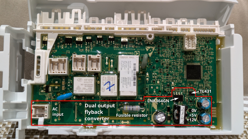
First: the fusible resistor is a protective component that is designed to burn out when something else fails. While there’s no harm in trying to replace it, it is likely that it will burn out again immediately if there is a short somewhere else. In my case (and I suspect in the majority of cases) it is the LNK364GN power regulator that failed. This regulator is at the core of the flyback converter circuit that generates 5V and 12V voltages from the input AC supply. It is powered at all times and exposed to high voltage at all times even when the appliance is nominally off, which may explain its limited service life.
Now replacing that regulator? Fun. The whole board is potted. I tried cutting out the potting compound around the chip and feeding hot air into the hole, but I couldn’t get the chip off before both the surrounding potting compound and the plastic case started to bubble. Remember that this is a power regulator that is significantly attached to ground planes for power dissipation reasons.
Replacing the main board
Now, let’s say you give up and want to install a new main board. In my case this is an EWX14 board.
What I didn’t know, and what I know now, is that the programming of the EWX11/EWX13/EWX14 boards is specific to the appliance model. It is not simply a matter of entering diagnostic mode and changing the model like it is on some devices. You need a model-specific Model Configuration File (MCF) and Cycle Configuration File (CCF). Furthermore, even if you can obtain the Electrolux programming software (SidekickPC), the configuration files are not included in the software, you need a Sidekick portal subscription to get them.
Here’s the thing about washing machines though. You need them. Especially when you have a family. In my haste I bought a replacement EWX14 board from my closest parts dealer without checking that it was programmed for the correct model, and that is how I ended up in a world of pain. Even though the board was physically identical to the one I was replacing, I ended up with all sorts of strange behaviour. None of the washing cycles would finish: generally the washing machine would fill with water to a ridiculous level, do nothing for a long time, and give one of a variety of errors.
While the behaviour was somewhat random, I did notice that the spin speed selection was limited to 1200, versus 1400 in my formerly working washing machine, so that was a good hint that the model configuration was wrong.
Electrolux support wasn’t helpful. All they could do was to organize a technician visit with a lead time of around a month, which is entirely useless, I don’t know how anyone can wait that long (see above about needing a washing machine).
Copying configuration
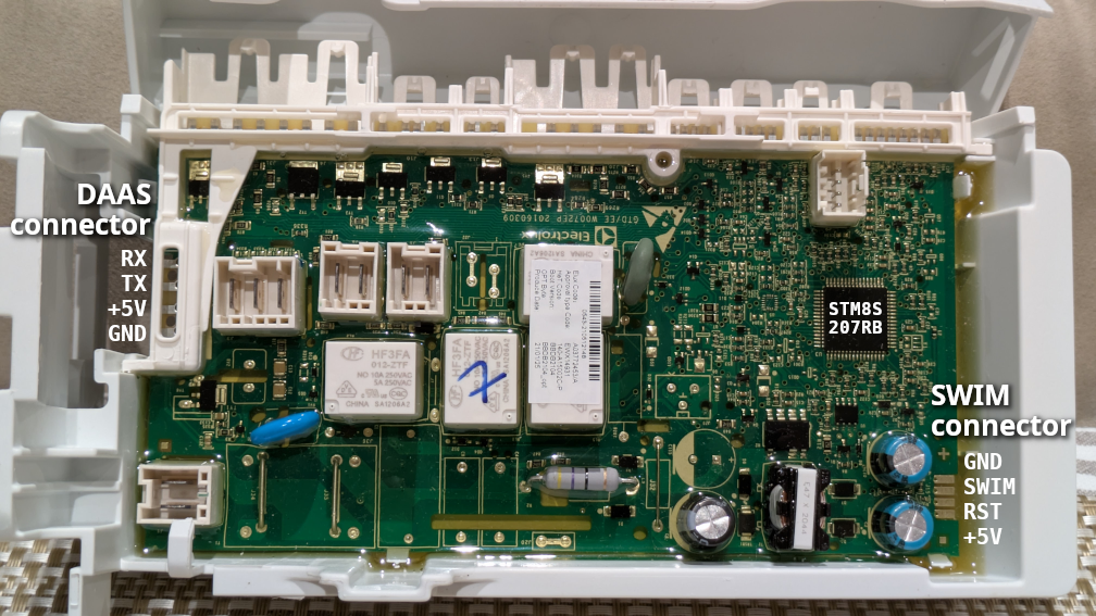
Not being able to obtain the configuration files from Electrolux, I realized that what I needed to do was to copy the configuration from my previous board to the new one. I managed to power up the digital parts of my old board by providing +5V on the SWIM connector used for factory programming (bottom right in the below picture). The SWIM protocol is standard on STM8 microcontrollers and I could successfully read out the configuration with an ST-LINK adapter.
Alas, the factory programming connector is normally under the potting compound, and I didn’t want to damage the potting on my new board. I wanted to program the new board via the ‘front door’ interface used by technicians. And so daas-util was born.
What is daas-util? Electrolux appliances use a serial protocol that Electrolux calls DAAS-EAP for diagnostic access. Surprisingly I could find no information about this protocol on the Internet (this is surprising given the number of Electrolux devices in the field). So, with some help from Claude AI, I reverse engineered this protocol and wrote a tool to enable reading and writing flash memory via this interface.
Extended addressing woes
The internal flash memory in the STM8 microcontroller is divided into a program memory area and a data memory area (the data memory area is referred to as EEPROM, although the physical technology is the same as the program flash). On EWX14 the bootloader, application firmware, MCF and CCF are all stored in the program memory area; as far as I know only error logs are stored in the data memory area.
Now STM8 is an 8-bit microcontroller with 16-bit addressing: most normal instructions use 8-bit data and 16-bit addresses. But 16-bit addresses can only access up to 64KiB of memory, and the STM8S207RB on the EWX14 has 128KiB of program memory. To access the upper parts of the program memory, specific instructions that use extended/far pointers are required, combining a 16-bit pointer with an 8-bit extended portion (‘bank’).
What stumped both me and Claude for a while is that the application firmware contains flash programming code, but no paths into it allow programming addresses beyond the 16-bit boundary. The bootloader also contains flash programming code, but it also does not support writes beyond the 16-bit boundary. We hypothesized, and verified from inspecting SidekickPC, that the programming software loads temporary code into the device RAM to perform programming. I am still a bit confused why both the application firmware and the bootloader have support for writing to flash bank 0 (only) — I cannot think of any programming use cases where one would not need to write upper banks, since part of the CCF is located there. Let me know if you have any ideas. Perhaps the code is there to enable writing to EEPROM to clear error logs, and the flash writing code came along with it for free.
In any case, I ended up writing my own flash writing plugin in STM8 assembly code and this is included with daas-util. Why did I write it in aseembly code and not C? Mostly because I could. In this day and age of Claude, I need to do stuff like this to keep up my brain skills. STM8 assembly code is actually very nice to write; it’s a CISC instruction set and many operations can be done in a single instruction. Embarrasingly, in my first version I introduced a bug where a register was not initialized on one path, resulting in some random flash scribbling and a moment of terror where my washing machine wouldn’t boot (fortunately, the bootloader was still intact so I could reprogram from the bootloader). Even more embarrassingly and impressively, Claude found the bug.
Final notes and tips
Now if you are ever in this situation of having to replace an EWX11/EWX13/EWX14 main board, my first recommendation is to make sure that you buy one that has been programmed for the right appliance model. If you cannot, or accidentally find yourself in the same situation as me, then daas-util is my gift to you.
To use daas-util you will need USB to TTL serial adapter that is capable of 5V operation. If your target main board has a working power supply, you can power up the board normally and leave the +5V pin on the DAAS connector unconnected (connecting only GND and UART pins). However, do note that the EWX14 power supply is not isolated and the output voltages are referenced to the AC neutral, so mains voltages may exist in the case of a fault, treat it with due caution. Alternatively, you can leave AC unplugged and temporarily power the main board with +5V either via the DAAS connector or the SWIM connector.
Beware the SWIM connector has a convenient + symbol next to it, which is right next to the pin which is definitely not +. Let’s just say, I’m glad that I always use a current-limited power supply.
If you want to check if your main board power supply is working correctly (versus having a broken power button or UI board), the red 4-pin cable harness from main board to UI board is a good place to check. It carries +12V power as well as a +5V signal (UART TX), and is easy to access from the top of the appliance. The two end pins should be +12V and GND, while the middle pins are the UART. At the UI board end, +12V is the separated pin on the connector; oddly the pinout is crossed over on the other end (maybe sensible for UART but odd for power signals).
If trying to temporarily power a board that has a failed regulator, note that you need to provide both +5V and +12V (as well as AC) for the washing machine to work correctly. For reference, the capacitor nearest to the corner of the board sits between the +5V and +12V rails.
If attempting to replace the LNK364GN, I would highly recommend taking the board out of the case (in theory this can be done with only minor damage to the potting, the potting will peel away from the case). I would also highly recommend removing the potting from a large surrounding area, as melted potting compound just makes the job harder.
STM8 programming postscript
I did discover something interesting about STM8 flash programming that might come in useful to someone in the future. The documented protocol for block programming is to sequentially write all bytes of a block (usually 128 bytes). What is not documented is what happens when you violate this assumption, which requires some understanding of how the programming buffer works. First, the byte writes are coalesced at 32-bit word level using the bottom two bits of the address; when four bytes have been written the word is pushed into the programming FIFO; when the programming FIFO is full the block is written. This has some implications:
- If you write to address 0x0, 0x1, 0x3, 0x3, the second write to 0x3 will clobber the first one, and the word will be considered complete, with the byte at 0x2 written with zero.
- Intra-block address bits ([6:2]) are ignored, you can write all words to the same word address, or write words to the block backwards, and the data will still be programmed to the block in the forward direction.
- As long as the writes hit the flash peripheral, the upper address bits are also ignored in all but the last write. The block to write is taken from the last write.
- Let us say your input data is 11 22 33 44 … and you start writing at some unaligned address like 0x13 (, 0x14, 0x15, 0x16, …), then the block referenced by the end address will end up written completely but with the bytes out of order (in this case 44 11 22 33 88 55 66 77 …).
Of course, I definitely do not recommend doing any of these things. But knowing the internals can help with debugging strange bugs.
