
 BETA
BETAI encountered an interesting problem recently. As part of a personal project related to magnetic resonance, I built a small coil set and pre-amplifier:
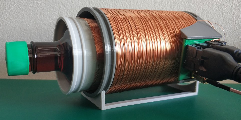
The pre-amplifier is located on the tiny green PCB; the signal received by the inner coil is amplified here and sent over a coaxial cable to an ADC. Since this is an Earth’s field system (EFNMR) with no large magnets, the frequency of interest is very low, around 2400Hz.
Now here is the strange thing: when I oriented the coil in a particular direction, the received environmental noise was very high, with lots of 50Hz harmonics. But when I oriented the coil in exactly the opposite direction, the noise was low. I repeated the experiment several times with the same puzzling result.
This really doesn’t make much sense physically. The induced voltage in such a coil is almost entirely due to changing magnetic field flux through the coil [footnote 1]. The AC noise should thus be identical in magnitude when the coil is reversed.
I did some random poking around to collect more data. While doing this I discovered something interesting: tightly bending the coaxial cable coming out of the pre-amplifier board produced this signal:

Experienced analog designers might immediately see where this is going: my amplifier is not stable. As the old adage goes: “to design an oscillator, try to design an amplifier…” It appears that bending a coaxial cable changes the complex impedance slightly and, given an unstable amplifier, this was enough to push my circuit into oscillation.
Understanding the cause
Here is my original pre-amplifier circuit:
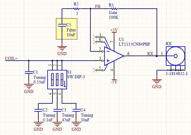
Notice the highlighted capacitor in the feedback divider. I thought I was being smart here by adding this capacitor to roll off the gain at low frequencies. The overall transfer function looks sensible in simulation, with a peak around the desired 2400Hz frequency:
But, if we simulate the open loop transfer function of the feedback loop, the
phase margin is very poor (and it is probably worse than this in reality due to circuit parasitics):
I think the problem is as follows: the phase shift through the op amp from inverting input to output is approximately -270° (-180° due to inversion, and -90° due to the low frequency output pole). So if the feedback circuit is capacitive and adds another -90°, we have a problem.
It is interesting to note that the instability was not immediately obvious until the system broke down into oscillation. If the input was a clean waveform, ringing might have been visible. But when the input is wideband noise, the output is wideband noise, with some extra spikes in the frequency domain. So if I hadn’t seen it oscillate, I might have spent a lot of time puzzling over why the output signal was so noisy.
Finding an alternative
After removing the capacitor, the stability issue appeared to be solved. However the signal now saturated the downstream ADC, due to insufficient suppression of 50Hz noise [our mains power line frequency in Australia]. The new transfer function shows why this is the case:
So I now needed some alternative way to suppress the ultra low frequencies especially 50Hz. There are three obvious places to do this:
- In the feedback path (but without causing instability)
- In the input path
- In the output path (after the amplifier)
With respect to (1), I think any linear circuit with the desired characteristic in the feedback path will create a stability problem. This is because there is less than two decades between 50Hz and 2400Hz and, (handwaving based on Bode plots), introducing a -20dB/decade gain slope at low frequency also introduces a -90° phase transition and takes the phase dangerously close to positive feedback.
With respect to (3), adding a decoupling capacitor after the pre-amplifier would solve my immediate problem of ADC saturation, but in this case the pre-amplifier would still amplify a lot of 50Hz noise, and I didn’t want to risk the op amp operating close to the rails and generating distortion products.
This leaves (2). Now I didn’t really want to add another RC filter stage in the input path, because my primary goal here is low noise and I was concerned about the Johnson noise of any extra resistance.
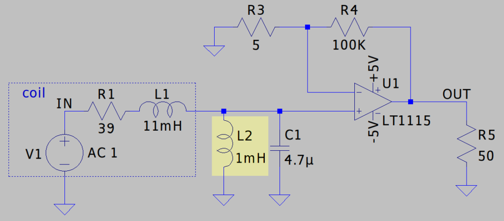
So what I ended up doing is to hack a bypass inductor across the coil. Intuitively speaking, this bypasses away the very low frequencies. More technically, it adds a zero at DC and a pole at a medium frequency, approximately 500Hz in my circuit when all of the components are considered [footnote 2].
This adequately suppresses the 50Hz signal and, since this is just a research project, it is more than sufficient for my needs. But if anyone has any other good ideas, I’d be interested to hear them.
Footnotes
[footnote 1] I make the statement that “the induced voltage in such a coil is almost entirely due to changing magnetic field flux through the coil”. The solenoid is very very small compared to the wavelength at the desired frequency (~125km), so any electric field gradient can be ignored. Under these conditions, the solenoid can be thought of purely as a magnetic field detector rather than a conventional antenna. I did, out of interest, put the geometry into an antenna simulator, and the result was a zero radiation pattern (to the limit of the simulator’s accuracy). Now in reality a solenoid or current loop with a changing current does radiate electromagnetic waves — my previous post should provide some intuition why this must be so — and using reciprocity principles we can assume that it also absorbs electromagnetic waves. But the far field radiation term is proportional to 1/λ2 and becomes negligible for large wavelength λ.
[footnote 2] Interestingly, this pole frequency is independent of the exact bypass inductor value L2, the RL filter is dominated by the coil’s R1 and L1. But using a small inductor here affects the overall gain (consider that we are shorting more signal to ground). It also affects the frequency of the LC double pole as L2 is effectively in parallel with L1 from the point of view of the LC resonance; if L1||L2 becomes small then C needs to be large to keep the LC pole frequency around 2400Hz. So I chose an inductor value that is reasonably large, while still being small enough that its series resistance can be low.

Hi,
I am assuming this is for proton magnetic resonance.
The 1mH inductor attenuates 50Hz, but also attenuates signal and reduces detector coil Q.
If you want to attenuate the 50Hz more than the signal then use a null filter. That is a shielded 50Hz resonant series LC wired in parallel with the sense coil. If necessary add additional stages to the null filter. Or even convert to a high pass peaked at the detection frequency, but this is a lot more tricky because you need high impedance to keep the detector coil Q high.
Or better yet make the amplifier 3 stage. Peak the coil at the detection frequency. Stage 1 is a low noise, low gain buffer, stage 2 is a high pass filter peaked at the detection frequency, and stage 3 to bring the level up to ADC levels. Stage 2 could be an LC filter.
Capacitance from inverting input to ground is a stability nightmare. See high speed photodiode amplifiers. The simplest answer is add capacitance to the feedback resistor.