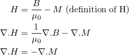
For a long time I thought of the H field as being generated by free currents only. The problem with this view is that it leads us to make erroneous assumptions. We know from the definition of H that:
![]()
The magnetization M is 0 outside of a material. So if we assume that H is due to free currents only, one would conclude that the magnetic field/flux B outside a material is also a function of free currents only – e.g. the external magnetic field of a solenoid would be independent of the material the core is made of. However, as seen in my previous post, this is not true. Also, one might conclude that permanent magnets have no external magnetic field, which is clearly not true either…!
Actually while ∇.B = 0 everywhere (there are no magnetic monopoles), ∇.H ≠ 0. The H field has sources wherever ∇.M ≠ 0:
(1) 
In other words if we want to calculate the magnitude of the H field throughout space, not only do we need to consider free currents (which produce circulation in the H field), but also material boundaries and other areas where M is non-uniform (producing sources in the H field).
Nonetheless, in typical elementary problems where we integrate around a closed loop, only the curl is important and we can still write for example ∮H.dl = Ipiercing (plus the dE/dt term if relevant).
Props to Griffiths’ Introduction to Electrodynamics section 6.3.2 for helping to clearing up this confusion in my mind.

 BETA
BETA
Hello, I am trying to clarify the field that exists within the core of a rectangular x section ferrite toroid of Ufer say 156 E-6 Wb/A m (typical of type 61).
The catch is that it is driven by one copper wire running down the inner wall. There is no full loop around the outside wall. What has been found is that the L of this arrangement is the same as for a copper foil liner (driven by a VNA at 1 Mhz).
My pseudo theory* is that the single wire forms a rotating flux underneath itself and this then pinches off , ready to combine with adjacent areas of flux – analogous to the x section of a solenoidal coil in air. at the same time as this first “domain” is created , others are generated but at much lower magnetic flux intensity around the ring (the toroid is flat on your desk and you are looking down on it ). These variable strength domains exist all around to the Pi radian pt opposite to the wire. The “domains ” combine basically as that are created and form a complete flux ring. This ring then settles down , some how, to a constant B value at every radial x section. B could potentially vary as 1/r radially. The simple analysis of an air cored toroid says it does but I’m not sure this remains valid for a ferrite cored toroid.
*The alternative is that the wire magically creates a circular B field in the toroid , of constant strength as we travel circumferentially and this is done regardless of radial distance from the wire. I don’t like magic in such an explanation.
This is not a commercial or school project it’s part of a discussion with a ham radio guy.
Continuing on the Cu wire in ferrite (long tube L/r = 4.5 in the test case). Note that there is no explicit ampere turn to create mmf . This of concern but in the analysis of a square section toroid (to get L ) the top and bottom (radial) wires of a wrap are ignored. It seems that the outer radius wire and current therein only contributes to Nsquared and in fact contributes negligible Magnetic flux density to the core. It may be that when the number of turns reaches 8 or so the Bfield from the outer wire(s) start linking and creating circular flux. That’s another problem.
As far as the tubular copper core problem (as compared to the single wire run ) – I’d look at this as as being say 20 individual wires each carrying 1/20th of the total current with infinitesimal width longitudinal air slits between them. Each wire will create its own field directly under it and these rotary B fields should all link at the instant of creation and create a uniform circular field. The alternative reading is that there is the traditional 1/r H field outside the hollow conductor and it is simply multiplied by Uferrite. The first version of the flux creation was simply to have something that was geometrically similar to the @single wire @ case.
I have a copy of Hayt Engineering Electromagnetics and it has very little treatment of Toroid type topics.
* THe two radial wires of a core wrap are possibly ignored on the basis that current is flowing in opposite directions in them. However the B fields created will only cancel the centreline. In order for the B field to completely cancel then it must be created uniformly through the core (in the axial direction) by the top and bottom radial wires. Perhaps that’s what happens in a type 61 material ferrite. I suggest this material because it has essentially no Rs (real resistive component under test with a vector flux meter ) up to about 10 Mhz so it is easier to handle mathematically.