MEMS oscillator frequency increase from helium

You may have heard of the incident where a helium leak suddenly disabled many iPhones at a medical facility. The root cause tiny MEMS oscillators being susceptible to helium leaking into their hermetically-sealed casings is interesting but not especially surprising. Helium is the second lightest element in the periodic table; helium atoms are tiny and have a knack for diffusing through all sorts of barriers.

What is very interesting, though, is that the helium exposure causes the frequency of the oscillator to go up rather than down (at least initially before more serious failures occur). In an experiment performed in a YouTube video from Applied Science, the frequency increases from 32768.24 Hz to 32768.70 Hz (14 parts per million) before device failure. In a research paper, which exposes a (different) MEMS oscillator to helium at high pressure over 50 hours, the frequency increases from 30418 Hz to 30501 Hz which is over 2700 ppm!

If the oscillators weren’t hermetically sealed, then the frequency increase would be understandable helium is lighter than air, and we all know what happens when we breathe in helium. But normally the oscillators are under near-vacuum conditions. Intuitively one would expect the addition of helium atoms to slow down the oscillation, either via gas damping or mass increase. Neither the YouTube video nor the mentioned research paper explain why the frequency increases.

Continue reading
Posted in Physics | Leave a comment

Android device encryption hang at Time remaining 00:00

Recently I had a frustrating problem while trying to enable full disk encryption on my Android device (Motorola G3 “osprey”). Every time the encryption process would hang forever at:

Encrypting
Wait while your phone is being encrypted.
Time remaining 00:00

After forcibly rebooting the phone, any password (even the wrong one) would result in a message like:

Decryption unsuccessful
The password you entered is correct, but unfortunately your data is corrupt. To resume using your phone, you need to perform a factory reset. When you set up your phone after the reset, you’ll have an opportunity to restore any data that was backed up to your Google Account.

This same message appeared even after the suggested factory reset – from this state, the only way I could find to restore the phone to working order was to format the data partition.

I looked into the source code, and it turns out that this problem happens if the encryption finishes successfully but the final writing of encryption metadata to the metadata partition (or the final test mount) fails for some reason. Normally the phone would restart soon after completion and the time remaining screen would disappear, but in this case nothing tells the user interface to report that an error occurred so it just sits there.

Debugging this sort of problem is not too difficult if you can plug in the phone via USB and view live logs with adb logcat. The good news is that the logs output from the encryption process are quite verbose. The bad news is that since the encryption process is done as part of a restart – with only a minimal system running and without user configuration loaded – adbd may not be running at this point to allow connection. To allow debugging this, I built my own Android image with adb enabled at boot by making these changes. (Building Android from source is daunting but easier than you would think… mainly it just uses a lot of Internet bandwidth and disk space.)

In my case – unofficial LineageOS 16.0 on my osprey device – the root problem turned out to be incorrect SELinux rules that denied vold (the volume manager daemon) permission to the metadata partition:

 D vold    : cryptfs_enable_inplace_f2fs success
 E Cryptfs : Cannot open footer file /dev/block/bootdevice/by-name/metadata for put
 W Binder:256_2: type=1400 audit(0.0:19): avc: denied { read write } for
             uid=0 name="mmcblk0p26" dev="tmpfs" ino=9642 scontext=u:r:vold:s0
             tcontext=u:object_r:block_device:s0 tclass=blk_file permissive=0
 I Cryptfs : cryptfs_check_passwd
 E Cryptfs : Cannot open footer file /dev/block/bootdevice/by-name/metadata for get
 E Cryptfs : Error getting crypt footer and key
 E Cryptfs : Could not get footer
 E Cryptfs : Encrypted filesystem not validated, aborting

To work around this I added a hack to system/sepolicy/vold.te in my Android build tree to allow vold access to all block devices… I’m sure there is a better way but this helped me to get back up and running quickly.

 allow vold block_device:blk_file { create setattr unlink rw_file_perms };

I hope this helps someone else if they run into this same frustrating problem!

Posted in Computing | Leave a comment

WebEx audio input hang on Linux (Chrome/Chromium bug)

If you have been connecting to WebEx meetings on Linux using Chrome/Chromium versions 79 or 80, you might have run into issues where your microphone randomly stops working and other participants cannot hear you. When trying to reconnect to the meeting, the connection process might hang for a long time. In Chrome’s Task Manager you will find that the “Utility: Audio Service” thread is using 100% or 200% CPU.

While WebEx triggers the bug most frequently, it is not a bug in WebEx: it has also been reported with Bluejeans and Gotomeeting and other conferencing solutions that use WebRTC technology. It is a bug in the PulseAudio backend in Chrome 79 and Chrome 80. I spent some time tracking this down, although someone else beat me to fixing it (no complaints). Here is the bug report and the fix.

The good news is that it’s fixed in Chrome 81.0.4044.62 and later, so the solution is to upgrade Chrome/Chromium. I am making this blog post as a note for anyone else who is looking for the solution to this problem.

Technical detail:
Every 1.5s WebEx refreshes the microphone/speaker/camera list by calling the JavaScript function navigator.MediaDevices.enumerateDevices(). When using PulseAudio, Chromium’s underlying implementation of that function calls, amongst other functions, AudioManagerPulse::GetInputStreamParameters() which is where the bug is. This function fails to lock the PulseAudio mainloop lock before calling into pa_context_get_source_info_by_name() in the PulseAudio library. The pa_context_get_source_info_by_name() function sends a request to the PulseAudio server and enqueues a dispatch entry so that the library knows what to do when the response arrives. Because of the lack of locking, there is a race condition: if another Chrome thread is executing in the PulseAudio library at the same time, the PulseAudio library’s dispatch queues can become corrupted.

Posted in Computing | Leave a comment

H field and material boundaries

For a long time I thought of the H field as being generated by free currents only. The problem with this view is that it leads us to make erroneous assumptions. We know from the definition of H that:

    \[ B = \mu_0(H+M) \]

The magnetization M is 0 outside of a material. So if we assume that H is due to free currents only, one would conclude that the magnetic field/flux B outside a material is also a function of free currents only – e.g. the external magnetic field of a solenoid would be independent of the material the core is made of. However, as seen in my previous post, this is not true. Also, one might conclude that permanent magnets have no external magnetic field, which is clearly not true either…!

Actually while ∇.B = 0 everywhere (there are no magnetic monopoles), ∇.H ≠ 0. The H field has sources wherever ∇.M ≠ 0:

(1)   \begin{align*} H &= \frac{B}{\mu_0} - M \;\textrm{(definition of H)} \\ \nabla.H &= \frac{1}{\mu_0}\nabla.B - \nabla.M \\ \nabla.H &= -\nabla.M \end{align*}

In other words if we want to calculate the magnitude of the H field throughout space, not only do we need to consider free currents (which produce circulation in the H field), but also material boundaries and other areas where M is non-uniform (producing sources in the H field).

Nonetheless, in typical elementary problems where we integrate around a closed loop, only the curl is important and we can still write for example ∮H.dl = Ipiercing (plus the dE/dt term if relevant).

Props to Griffiths’ Introduction to Electrodynamics section 6.3.2 for helping to clearing up this confusion in my mind.

Posted in Physics | Leave a comment

Magnetic field of a ferrite core solenoid

Consider a solenoid made of wire wrapped around a rod made of iron, ferrite, or other ferromagnetic material:

Image by Svjo via Wikimedia Commons

It is well known that the magnetic field will be significantly stronger inside such a solenoid, compared to an air core solenoid. The ferromagnetic core becomes temporarily magnetized and reinforces the magnetic field. But what I’m more interested in is: what is the effect of the ferromagnetic core on the field outside the solenoid, some arbitrary distance away? This question is interesting when using such a coil as part of a magnetically-coupled data or power transfer system, or when considering the electromagnetic interference produced by such a solenoid.

Some sources seem to suggest that the field will be confined more closely when a ferromagnetic core is used, as is the case for ferrite-core transformers. Other sources seem to suggest the opposite, namely that the ferromagnetic core increases the range of the field. Meanwhile a naive application of the Biot-Savart law would suggest that the field outside the solenoid does not change. Which of these is true?

Simulation

To answer this question, I ran a simple simulation with and without an iron core in the excellent FEMM field solver. Here is a picture of the results:

This is an axisymmetric simulation around the z axis. To picture the results in 3D, mentally revolve the half-circle about the z axis at the left. The outer sphere can be ignored, it is just the boundary of the simulation volume.

The conclusion from the simulation is that — at least for a fixed current — the magnetic field is higher outside the solenoid (at any given distance) when an iron core is added.

But surely as we learnt in physics classes, we should be able to calculate the external magnetic field by summing up all the current elements of the solenoid, per the Biot-Savart law? Why does adding an iron core make a difference?

I believe the explanation is that there are “bound currents” at the boundaries of the iron core which also need to be included in any such piecewise calculation of the magnetic field. This stackexchange answer has some good diagrams that help to explain how these bound currents come about.

Constant energy comparison

Now it should be noted that the above simulation has assumed a constant current of 1A in both cases. When the iron core is added, the inductance of the solenoid increases and we had to pump more energy into the solenoid to produce this 1A steady state — so perhaps it’s not surprising that the field is stronger outside the solenoid. To make a more “fair” comparison, I reduced the current through the iron core solenoid to produce the same total energy storage:

Notice that, at least for this geometry, the external magnetic field is still higher at any given distance.

“Return path”

So why do people consider iron/ferrite cores to confine fields more tightly? Well, the issue with the above solenoid design (or perhaps feature if you are trying to increase range) is that the return path of the magnetic field lines is through air and not through iron. We have boosted the magnetic field within the iron, but we’ve ended up with most of the field energy in the air.

If we were to put the iron all the way around the solenoid, which is closer to the usual design of transformers, the result does indeed confine the fields tightly (N.B. I have used the same colour mapping here so that it can be directly compared):

I hope that this post helps to clear up some confusion and might be of help the next time someone is searching for information about the external magnetic fields of ferrite core solenoids (like I was earlier today)! If you think I have got anything wrong, please let me know.

Posted in Physics | 5 Comments

Designing and making a ring

Recently I designed an engagement ring for my (now-)fiancée, from scratch. This was a fascinating and challenging process, and gave me a new appreciation for both the art and engineering of jewellery design.

The first step in the process was to make a collection of existing designs that we both liked. Heather already knew that she liked diamonds with a step cut shape (such as the emerald cut) so this narrowed it down. Here is one of the pages of our initial design exploration:

We visited a local jeweller, who showed us some designs in similar styles. There were a few features that were missing though; for example, I really liked the gap between the center stone and halo in the vintage ring. For practical reasons I also wanted to design a ring that had a low side profile, as I had nightmares about Heather losing a ring finger in machinery.

Granted, I’m sure a good jeweller could have designed something fitting the bill, but I had been doing a bit of CAD recently and I thought… how hard would it be to design a ring myself?

(The answer, it turns out, is that it’s surprisingly hard if you haven’t done it before. I did intermittently find myself wishing that I was working more closely with a jeweller, but it was a labour of love…!)

Here you can see the evolution of my design in Onshape, from an initial shape, to the detailed design of halo and shoulder, and then some final changes based on manufacturing feedback:

The final design was manufactured using a lost wax casting process. In this process, the model is first 3D printed in a wax-like resin. A flask is placed around the model and flooded with a plaster-like investment material. Once the investment has hardened, the wax model is melted out, and metal is cast in the chamber that remains.

The printing and casting was done by Pure Casting in Sydney, who did an amazing job. I wasn’t sure how the design on the shoulder would turn out; the raised design is only about 0.2mm high, and about the same in line width, so it requires very high resolution. But it turned out perfectly. Pure Casting also arranged polishing and stone setting for me. (I thought briefly about doing it myself, but this time I decided against it!)

Here is a photo of a draft cast in silver, unpolished and without stones:

And here is the final ring:

Here are some notes about this design:

  • In the final design, the ring is manufactured in two pieces and soldered together at the end, otherwise it would be difficult to polish in between the parts. (Thank you to Gillian at Pure Casting for this and other good advice.)
  • The majority of ring designs use round/cylindrical prongs, but I used rectangular prongs here. I felt that this better suited the angular nature of the emerald cut, and I also think that this shape may be slightly better mechanically (a round prong with the same diameter has less metal, while a round prong with the same area is harder to bend over). Originally I added taper angles to the prongs, but it was suggested to keep them simple and leave finishing details to the setter.
  • The majority of designs use flat or nearly-flat halos, but each face of this halo is inclined outwards significantly (35 degrees). Again, I wanted to echo the faces of the emerald cut, as well as providing a softer side profile to the ring. This means, however, that each of the eight faces of the halo is in a different plane, and this made the placement of the halo diamonds and prongs more challenging.
  • To make sure the dimensions were right, I measured the actual diamond dimensions and angles from macro photos, and built a CAD model of the diamond. I did find a lot of curiosities; for example, I was also expecting the corners of an emerald cut to be cut at 45 degrees, but in fact they were around 42 degrees, and one corner was slightly ‘off’. The key with any gem setting, therefore, is to design in some tolerance.

The biggest challenge in the design was the engraving-like design on the shoulder of the ring. I was inspired by vines but, not having the artistic ability to draw vines, I made it more geometric. The final engraving design took all of my CAD knowledge, and some spline mathematics, to implement.

Heather and I are both thrilled with the end result. Thank you again to Onshape for building an awesome CAD system, and to Pure Casting for turning my design into reality.

Posted in Other | Leave a comment

Splines in Onshape, part 2

In part 1, we talked about 2D splines and how they can be created in Onshape sketches. In this second part, I’ll briefly cover drawing splines directly in 3D, and then discuss offset curves, which are the original reason I started on this long journey delving into Onshape curves. Continue reading

Posted in Computing | 5 Comments

Splines in Onshape, part 1

Introduction

First can I say how much I love Onshape. I have no association with the company other than being a user, so you can trust that this is real, genuine puppy love. Onshape provides much of the functionality of parametric CAD systems such as SolidWorks in your browser, which at first sight seems like magic. Since I’m a Linux user and the native CAD landscape on Linux is quite limited, being able to do CAD in a browser works brilliantly for me. Even better, it’s free for non-commercial use.

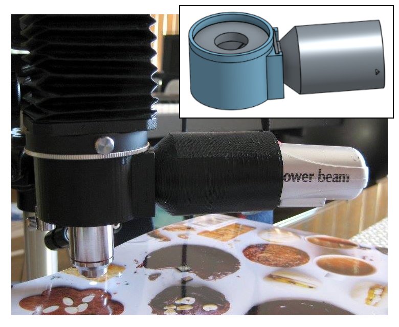
My first little project in Onshape, several moons ago, was a vertical illuminator for my home-brew microscope. The problem I had was that when using high magnifications — which require the lens very close — I couldn’t get enough light in under the lens to illuminate opaque samples. A vertical illuminator is the solution to this problem, sending light down through the lens via a beamsplitter. I designed the physical parts in Onshape, exported to STL format and uploaded to Hubs (previously 3DHubs); a local maker printed the parts and within a few days I had it back and working.

Scripting in Onshape

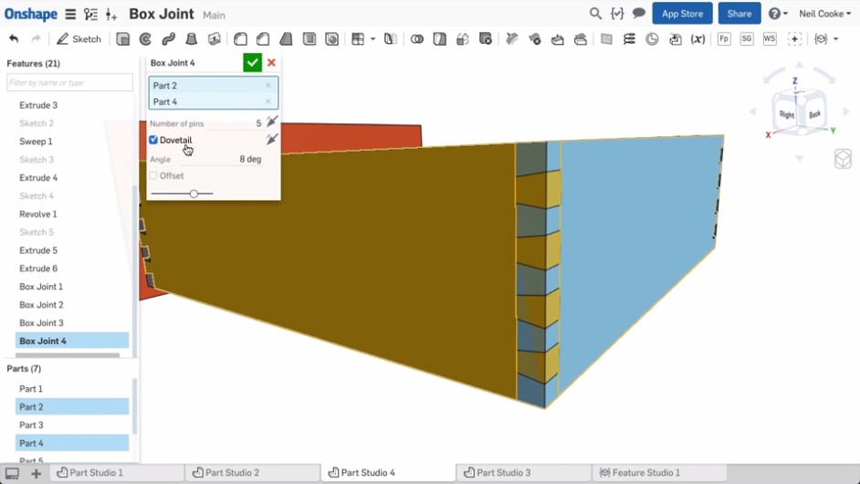
Onshape has a scripting language called FeatureScript. FeatureScript allows extending the Onshape interface with domain-specific tools (features as they’re known in Onshape). For example, if you are doing furniture design in Onshape, you can write features that produce panels and joints and then do high-level design in the user interface, rather than having to work with low-level primitives such as lines and boxes. Clearly this can be a huge boon to productivity. Here is a screenshot from one of the Onshape demonstration videos showing a custom box joint feature that, once created, can be used just like built-in features:

As a programmer and perfectionist I like the idea of writing code to simplify the CAD process rather than spending hours placing parts in a GUI. Prior to Onshape I’ve used OpenSCAD a few times. But for complex designs it gets difficult to mentally keep track of what’s where without having a live preview, and OpenSCAD rendering can get very slow once you start chamfering, filleting and making things pretty. This is where Onshape and FeatureScript shine.

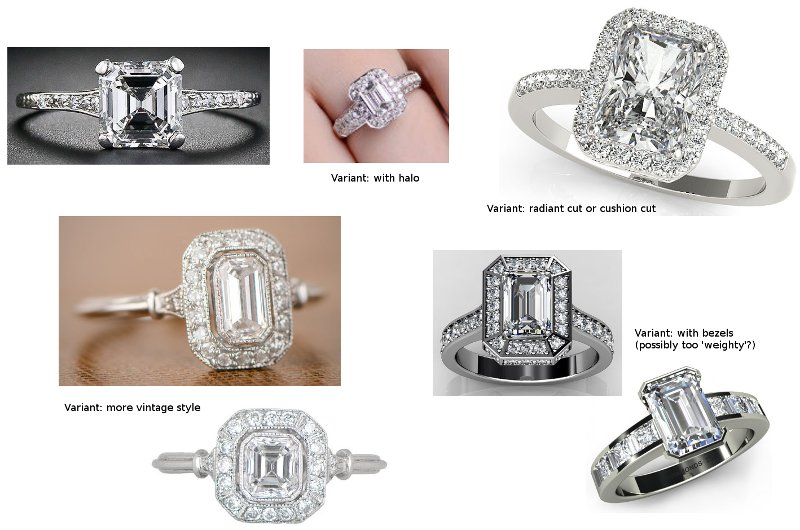
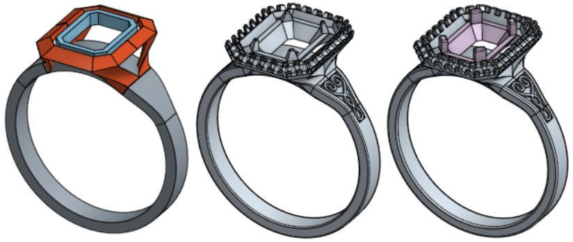
Recently I’ve been doing a bit of jewellery design in Onshape, and this involves a lot of curves and curved surfaces. While I can approximately create the curves I want in the GUI, I wanted to do it programmatically in FeatureScript. Unfortunately a number of the functions that I needed to use were minimally documented so I had to do a lot of trial and error in the process. This article is an attempt to explain some of the missing links for those following in my footsteps.

Onshape is still being developed at a breakneck pace, and since I started writing this article there are now a number of new features related to curves including the option to directly create splines in 3D. I’ll start, though, from the ‘traditional’ way of creating curves in Onshape — by creating them in a 2D sketch and then lofting/extruding/etc. — and I’ll briefly mention 3D curves later in the piece. Continue reading

Posted in Computing | 5 Comments

Dell Venue 11 Pro travel keyboard troubleshooting

Introduction

I recently purchased a pair of Dell Venue 11 Pro 7140 tablet computers — one for myself and one for my girlfriend. I figured this would be a good crossover device between a tablet and a laptop, and so far I’m not disappointed. One important reason I chose this model is because they are more easily serviceable than other comparable offerings like the Microsoft Surface Pro line; the Surface Pro is glued together in a way that is difficult to disassemble and reassemble, which makes me very unhappy. Batteries have a limited service life (as I know all too well from my last post), and I don’t want to throw away a perfectly good tablet in a couple of years just because the battery is not holding a charge. Even if you don’t have any interest in taking apart your own devices, I would encourage you to consider the fixability of your device and vote with your wallet against throw-away devices. Anyway, enough of that rant.

Together with my Dell tablet I bought a keyboard. There’s two types of keyboard available for the Dell Venue 11 Pro: a “slim tablet” keyboard (K11A), which is just a keyboard and touchpad, and a “mobile” or “travel” keyboard (K12A), which additionally has a battery in it. I chose the latter version with the battery inside so that I could get more battery life out of my tablet.

I ran into an interesting problem with the travel keyboard, or at least my unit. Sometimes after attaching it to the tablet, the touchpad didn’t work. Sometimes the whole keyboard wouldn’t work. Strangely though, if I disconnected the battery inside the keyboard or let it drain completely, it would always work reliably, so I knew that it was some interaction with the voltage from the battery. Continue reading

Posted in Computing | 2 Comments

Unlocking my Lenovo laptop, part 3

The decryption function

If you are just joining this story you may want to start at part 1.

In part 2, we discovered that a embedded controller update is performed by uploading a small ‘flasher’ program to the EC. This flasher program is then responsible for programming a new firmware image to the EC’s internal flash memory. However, both the flasher program and part of the firmware image are encrypted: the old (currently running) EC firmware decrypts the flasher program, and the flasher program then decrypts the new firmware update. This creates a bit of a chicken-and-egg problem that prevents discovering the encryption algorithm from firmware update files alone. Continue reading

Posted in Computing | 77 Comments