 BETA
BETAIn part 1 and part 2, we introduced the reverse sprinkler problem and tried to gain some theoretical insight. In this final part, we will simulate five different sprinkler designs and interpret the torque results.
The line-up
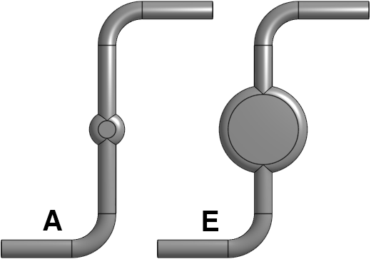
Five different sprinkler designs were drawn using Onshape and simulated using OpenFOAM:
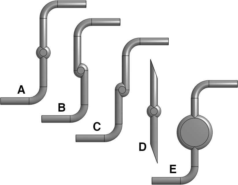
Design A could be considered the canonical sprinkler, with the center of each arm in line with the rotation axis. In designs B and C, the arms are deliberately offset to one or other side of the rotation axis. Design D is based on one of the designs in Beals (2017); it features a straight pipe cut at an angle, which turns out to function similarly to a bend. Design E is essentially the same as design A but features a larger hub. I’ve uploaded the designs and simulation control files to a Github repository.
Analysis of basic sprinkler designs (A, B and C)
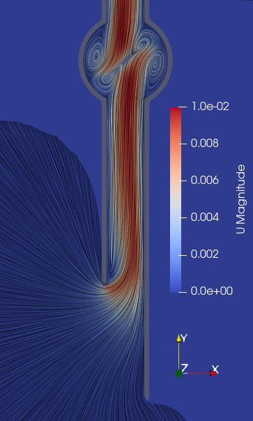
We will start from the offset designs, B and C, as they are relatively easy to understand and instructive to compare. Simulated fluid flow for the two designs is shown below (these pictures are produced via line integral convolution of the velocity field):
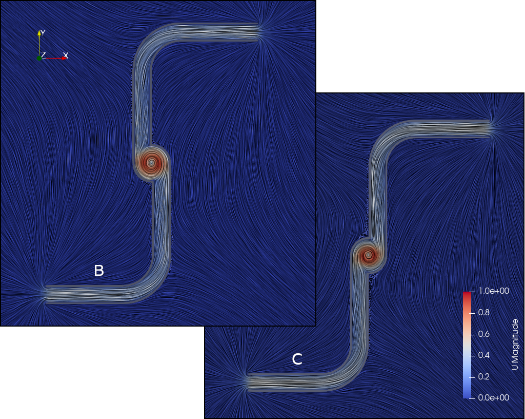
It should be clear that in both cases the fluid has angular momentum as it spirals down the “plug hole” in the hub. In design B the hub vortex is counterclockwise and in design C the hub vortex is clockwise. Therefore we would expect the sprinkler to turn in the opposite direction (clockwise for design B, and counterclockwise for design C), per the argument in part 2 of this blog post. This is confirmed by numerical integration of torque over the sprinkler body.
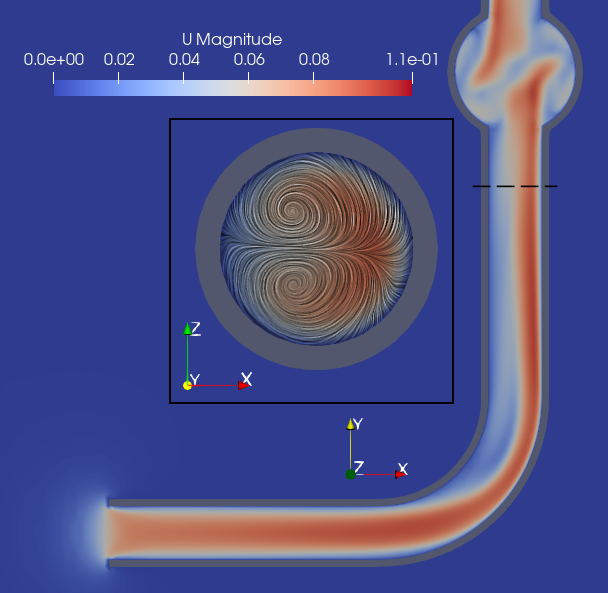
Now consider the simulated fluid flow for design A, shown both in the z=0 midplane (left figure) and at the bottom of the hub near the plug hole (right figure). The flow is colored by y-component to make it easier to see the direction of flow in each vortex:
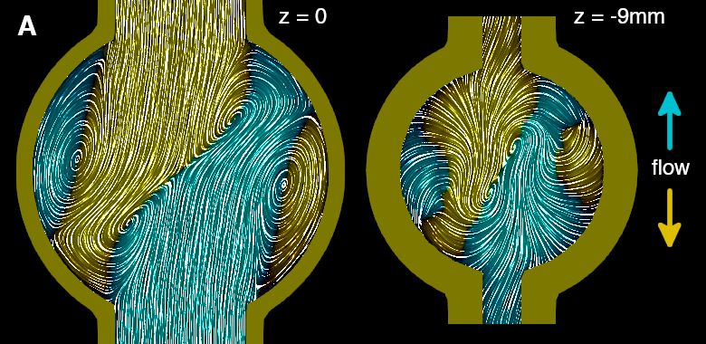
The four-vortex arrangement at the midplane is similar to that observed by Wang et al (2024). We observe that the counterclockwise vortices that lie along the fluid “collision line” are stronger and dominate the flow down the plug hole. Therefore we expect clockwise rotation, which is also confirmed by numerical integration of torque.
The following table shows numerical integration results for sprinkler torque and angular momentum efflux at the outlet, demonstrating the principle that we showed theoretically in part 2. While there is not a perfect agreement, the deviations are within the expected experimental simulation error1. Designs D and E are also included in this table and will be discussed shortly:
| Design | Integrated torque (μNm) | Angular momentum efflux (μNm) | Rotation direction |
| A | -0.072 | 0.071 | CW (reverse) |
| B | -0.169 | 0.167 | CW (reverse) |
| C | 0.168 | -0.168 | CCW (forward) |
| D | -0.079 | 0.076 | CW (reverse) |
| E | -0.027 | 0.027 | CW (reverse) |
Understanding the flow in design A
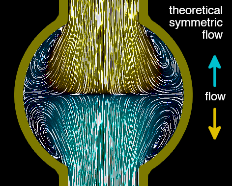
In design B and C, the off-axis arms can be seen to “force” the central vortex one way or another, and the resulting opposing rotation is intuitive. In design A, the flows from the two arms collide head-on. If the fluid flow in the arms was perfectly symmetric around the center line, the result would be a symmetric convergence like this, which results in symmetric outflow and no rotation (at least theoretically speaking):
However, in reality the fluid flow after a bend is not symmetric. The flow is displaced outwards, and there is some secondary flow in the transverse plane to satisfy continuity. This syndrome is known as Dean flow:
This asymmetric flow in the arms results in asymmetric flow convergence in the hub. How this actually translates into torque on the sprinkler is more complex than expected however, and will be discussed below in relation to design E.
Design D (angled inlet)
In design D, the pipe elbow is replaced with a straight pipe cut at an angle. It turns out that the net effect is the same: the pipe flow is displaced outwards, producing a hub flow and resulting torque that are similar to design A:
As a side note, Beals (2017) tries to explain the rotation of this sprinkler design by stating that “in this scenario the [external] streamlines must curve in the direction of the pipe axis, and this reflects angular momentum given to the surrounding fluid”. However, our theoretical argument in part 2 applies equally well to this design, and suggests that the angular momentum exchange occurs at the outlet and not the inlet. This view is supported by the simulation results in Table 1.
Design E (larger hub)
Design E is equivalent to design A but with a larger hub. It turns in the same direction as A (clockwise), but with a lower torque. Why? The flow in the arms is calibrated to be the same, so if we follow the “inner rocket” argument of Wang et al, the torque should be the same. If anything we might expect design E to result in higher torque, since the arm is slightly shorter and thus the Dean flow asymmetry is slightly higher at the arm-hub interface.
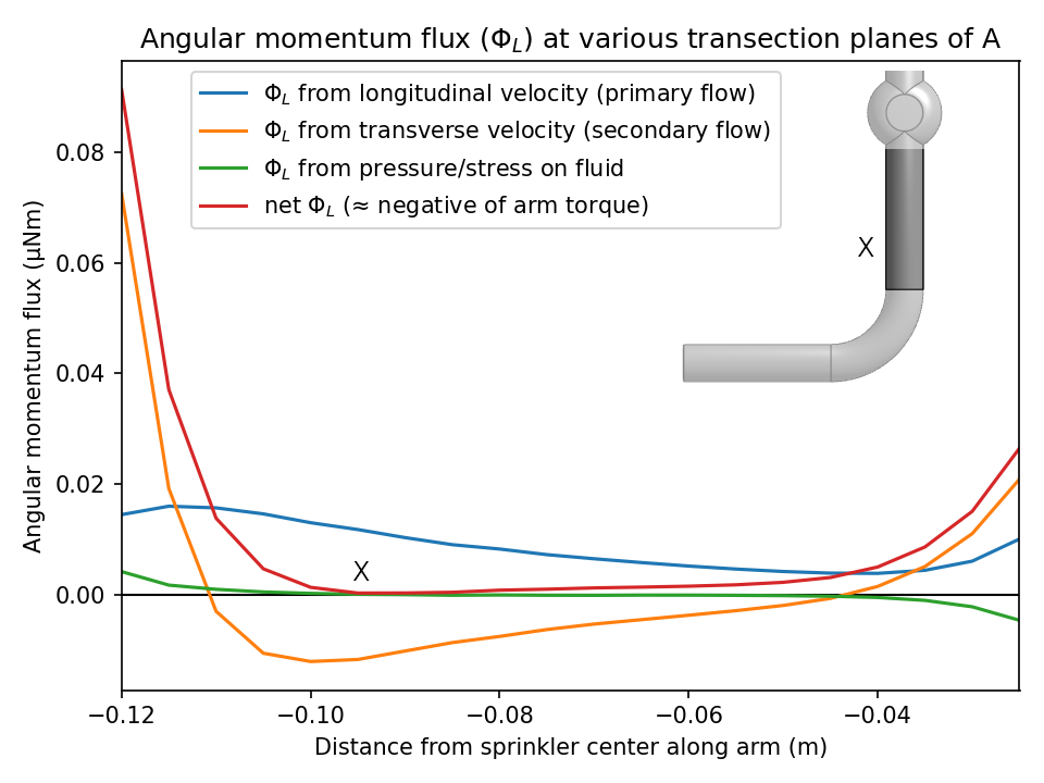
To help explain where the forces and torques act, here is a plot of the cumulative torque on the sprinkler A, transected by various planes. That is, we add up the torques acting from the end of the arm up to the given plane. The (negative of the) angular momentum flux through the same planes within the sprinkler pipe is also shown and matches closely3, reinforcing the points made in our earlier theoretical analysis.
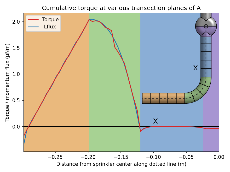
At the open end of the pipe, there is some negative (CW) torque due to pressure forces on the pipe end. This is rapidly overcome by frictional (shear stress) forces on the side of the pipe, which produce torque in the positive (CCW) direction. At the elbow the pressure forces cancel this out, as argued from an x-momentum balance in part 1. There is some slight overshoot apparent, before a return to near-zero at some plane X. That is, the part of the arm below plane X produces near-zero net torque and can be ignored! The final straight part only makes a small negative contribution, and the majority of the final torque is from the arm-hub interface (more on this shortly).
Similar analysis of the torques in design B and design C makes this even more stark:
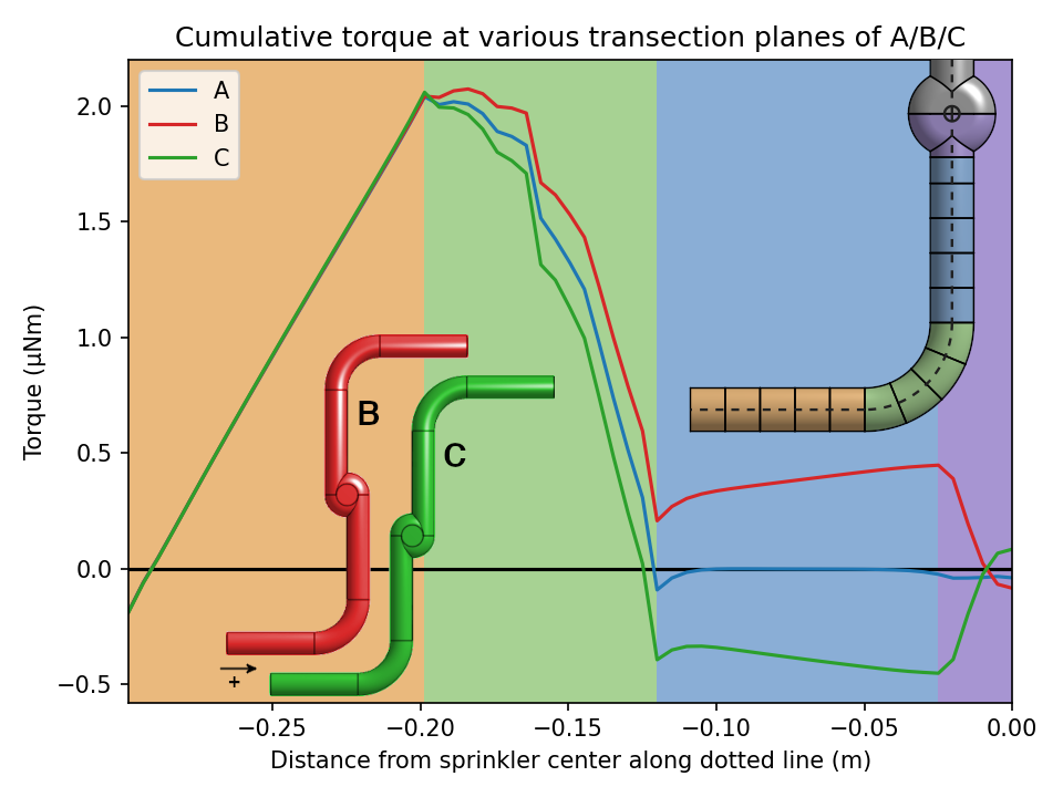
In design B (red line), the torque on the arms is actually counter-clockwise (+), even though the overall net torque is clockwise. In design C, the torque on the arms is actually clockwise (-), even though the overall net torque is counter-clockwise! The cumulative torque switches sign only as we enter the hub, the purple region at the very right of the graph.
How can this be? If we naively apply the “inner rocket” approach, the angular momentum of the fluid exiting the arm in design B would seem to be counter-clockwise (+), so the torque on the arms should be clockwise (-), contrary to the graph. But remember that the net momentum flux out of the fluid volume is not only a function of the fluid velocity, but also stresses on the fluid volume. In designs B and C, the fluid pressure (which is applied entirely on one side of the axis) dominates the angular momentum flux equation. Meanwhile in designs A and E, the angular momentum flux from the displaced primary flow is almost completely cancelled4 by the angular momentum flux from the Dean vortices, which – despite having a low velocity – act on a longer arm. This explains the near-zero torque from most of the sprinkler arms.
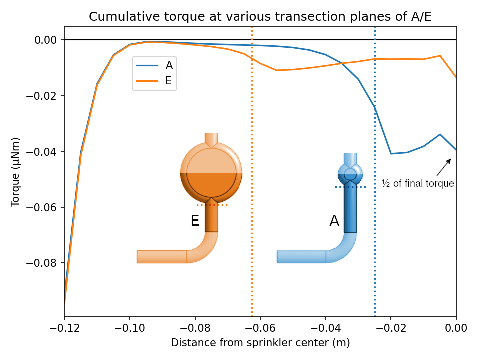
The following plot, using the same methodology but zoomed in, shows more clearly that the the final torque primarily arises from the arm-hub interface. This is where the difference between designs A and E becomes apparent. In the smaller hub of design A, the torque component at the arm-hub interface is larger, due to higher pressure gradients in the smaller hub. These pressure gradients permeate into the arms somewhat, so it is difficult to cleanly separate the hub and arm contributions. However simulations with longer arms confirm that torques along the arm section are small and approximately linear, and the deviation from linear can be attributed to the approaching hub interface.
The crux of the matter
What we see in all of these cases is that:
- The dominant direction of hub circulation is consistent with that intuitively expected from the jets coming out of the arms. This then determines the direction of circulation at the outlet and the direction of the net torque. Imagine a situation where the hub flows circulate in the opposite direction; assuming appropriate torques on the sprinkler, this does not violate momentum conservation. But the required pressure gradients for counter-flow are larger, and physics does not spontaneously produce such solutions (consider the Principle of Minimum Pressure Gradient, and the convective-diffusive nature of the Navier-Stokes Equations).
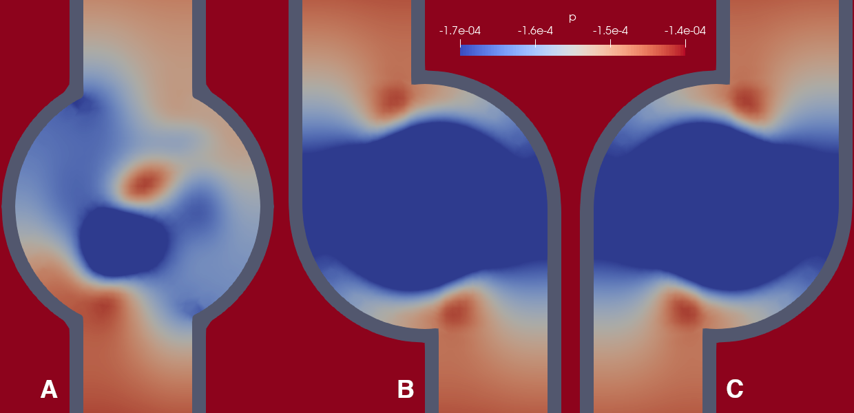
- The magnitude of net torque on the sprinkler actually appears to be primarily a result of pressure gradients near the arm-hub interface, where the incoming flow meets the circulating flow in the hub and thus must experience pressure forces. These pressure cells are shown in the following pictures. Note that the pressure scale is quite exaggerated to show these small pressure gradients; the fact that the torque arises from such a small detail might help to explain why the problem ends up being so fragile.
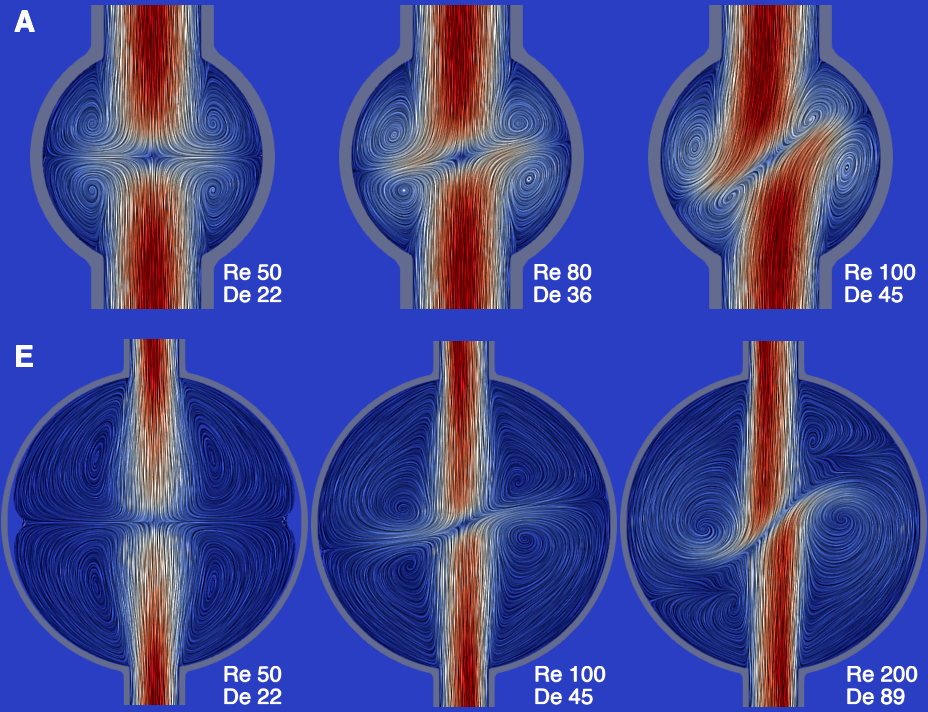
Flow at higher rates
The situation becomes even more complex as we increase the flow rate. The following figure shows simulated flows for designs A and E at a selection of different flow rates2. As the flow rate increases, the “collision line” between the flows in the hub becomes more inclined; the same trend is apparent in the videos from Wang et al (2024).
What happens if we continue to increase the flow rate? Clearly, it is not possible for the angle of the collision line to increase indefinitely, so either it must asymptote or there must be a transition to a different flow regime.
In simulation, what we see is the latter: the hub vortices become unstable and the hub flow becomes turbulent, even when the arm flows are still laminar. The following video shows a transient simulation of design E at pipe Reynolds number ≈ 500. The overlaid plot shows simulation results for the torque, using direct numerical integration of torques (black line) and indirect calculation from angular momentum flux at the outlet (green line):
The instantaneous torque is coupled with the turbulence and actually oscillates both positive (CCW) and negative (CW), with a bias towards the negative (CW) side. The average torque derived from outflow momentum flux is consistently negative (CW). This is not contradictory as it is only the long term time average of these two results that must be consistent.
If we take this simulation to be a feasible representation of reality, we would conclude that – for flow rates in this turbulent region – the sprinkler rotation is unsteady, with a net rotation in reverse (CW), and a degree of unsteadiness that depends on the inertia of the rotating body. This is loosely consistent with various experiments in the literature. The torque oscillation between positive and negative values is surprising but not physically impossible: consider our previous statements that the net torque is largely a function of pressure forces where arm flows meet hub flows; when the hub flows are turbulent, it makes sense that the net torque may be very unstable.
Concluding statements
In this series of blog posts, we did a deep dive into the reverse sprinkler problem, from an idealized theoretical treatment in part 1, to a more general theoretical treatment in part 2, and finally ending with computer simulation results in part 3.
Returning to the question “do all reverse sprinklers rotate backwards?”: it should be evident that the answer is no, as we can engineer a sprinkler such as design C which is expected to rotate forwards. For sprinkler designs such as A/D/E which have no obvious geometric bias, flow asymmetry in the arms results in a tendency towards reverse rotation, consistent with Wang et al (2024). However we find that the “inner rocket” view of Wang et al is not sufficient to explain the torque values experienced by our sprinkler designs, and actually we argue that the net torque is predominantly driven by pressure gradients where the arm flows enter the hub. As a result, the rotation depends on the hub design, and may be turbulence-coupled even at relatively low flow rates.
It turns out that something as simple as a reverse sprinkler can actually be very complex.
- Torque in particular is quite sensitive to meshing quality, since it involves summing a large number of almost-cancelling pressure torques and shear torques over the tessellated sprinkler surface. Therefore we suggest the angular momentum efflux, which is a simpler calculation over the plug hole, may actually be closer to the real torque value. ↩︎
- We define the flow rates in terms of Reynolds number for the arm flows and Dean number for the bends, although as is evident from comparing designs A and E, the flows are also characterized by the hub size, and perhaps one could define another dimensionless number that takes this into account. ↩︎
- The angular momentum flux values are smoother as they are summed on an interpolated plane, while the torque values are summed over discrete cells in the mesh. Also, in comparing the torque to the angular momentum flux inside the pipe, we are subtly ignoring some of the exterior flow stresses, as explained in part 2. This results in a discrepancy in the first point of the graph (at the inlet), but elsewhere the outside flow has negligible effect. ↩︎
- Here is a momentum flux decomposition for the post-bend pipe section of design A, showing the angular momentum cancellation which is maximal around plane X. We do not believe this is a general or theoretically perfect cancellation (the angular momentum flux from transverse velocity depends on the y distance from the center and for a longer arm, the bottom of the net ΦL curve crosses the axis). However the point stands that, at least in the geometries we have studied, the primary and secondary flows tend to largely cancel when it comes to angular momentum flux, which then means that the torques tend to cancel. ↩︎