
 BETA
BETAA short version of this post series is also available as a YouTube video here.
The reverse sprinkler is a physics problem that has long been a source of confusion and debate. It is sometimes known as the Feynman sprinkler problem after Richard Feynman who popularized it. Briefly: consider the type of garden sprinkler that rotates as water is ejected from it. Now submerse the sprinkler in a tank and reverse the fluid flow such that water is sucked in instead of ejected. Does the sprinkler rotate, and if so, in which direction?
Jenkins’ An Elementary Treatment of the Reverse Sprinkler (2003) has an promising title and is often cited as proof of non-rotation of the reverse sprinkler. But as Jenkins himself points out in a subsequent paper (2011), this original analysis is flawed1. The revised analysis resorts to a rather tortuous argument assuming an idealized contraction of the flow at the pipe entry. In any case such ideal fluid models can only tell us that the sprinkler does not rotate to a first order approximation.
Experimental studies have generally shown either no rotation or weak reverse rotation. The latest by Wang et al. (2024) provides a convincing explanation for reverse rotation, and is a remarkable piece of physics and engineering. However, after reading it, I still felt somewhat unsatisfied. The experiment shows that the studied reverse sprinkler rotates in reverse due to outflow asymmetry within the hub. I still had the question: do all “reverse sprinklers” rotate backwards, or can we build one that rotates forwards? Also, if all outflow asymmetry could somehow be compensated out, would there be any torque attributable to the inflow?
In this set of blog posts I will try to provide my own analysis of the reverse sprinkler. I start with an idealized analysis in this part to develop some intuition, extend it to arbitrary geometries in part 2, and proceed to computational simulations in part 3. Feel free to skip ahead if the material gets too dry. My simulation results in part 3 suggest that the direction of rotation is correctly explained by the model of Wang et al, but when considering the magnitude of torque, a more subtle mechanism is involved. To simplify the analysis, I will focus primarily on a model where the sprinkler is being temporarily held in place such that there is no actual rotation, and we consider the forces or torques at play.
First note: Blowing is not the same as sucking
Many people’s first response to this problem is to assume that the reverse sprinkler can be considered the opposite of the forward sprinkler. However, this is not the case.
In the case of fluid ejected from a pipe, the outgoing fluid parcels have collimated momentum, producing a directed jet. Meanwhile, fluid being sucked into a pipe can be considered a pressure-driven flow, where fluid parcels are “falling” toward the mouth of the pipe which is an area of lower pressure. These two flows are not a mirror image in any sense.
The spherical cow
We start with a very idealized treatment to gain some intuition. Consider the sprinkler pipe to be of negligible diameter and frictionless, such that fluid is falling inwards towards a single point of low pressure. In this case, the inward flow is essentially spherically symmetric:
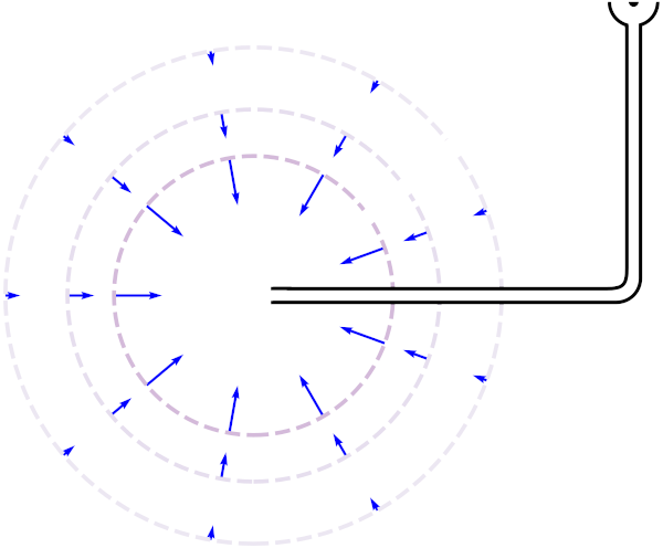
The simplest argument for the non-rotation of this sprinkler is one of global momentum conservation. The sprinkler can only experience a force (change in momentum) if momentum is exchanged with the outside world somehow. The sprinkler can only experience a torque (change in angular momentum) if angular momentum is exchanged with the outside world somehow.
If the inward flow is spherically symmetric, it does not carry any net momentum flux2. The outward flow into the hub is collinear with the center of rotation and so there is no angular momentum flux here either. Since the fluid does not change angular momentum, we can conclude that the sprinkler also does not change angular momentum. This momentum conservation argument may be intuitive to some readers. However, to get a better understanding, I will go through the process of drawing some control volumes and applying the standard integral methods taught in fluid mechanics classes.
Consider the following two control volumes CV1 and CV2. Both are within the fluid, and hug the sprinkler pipe apart from surfaces A, B & C:
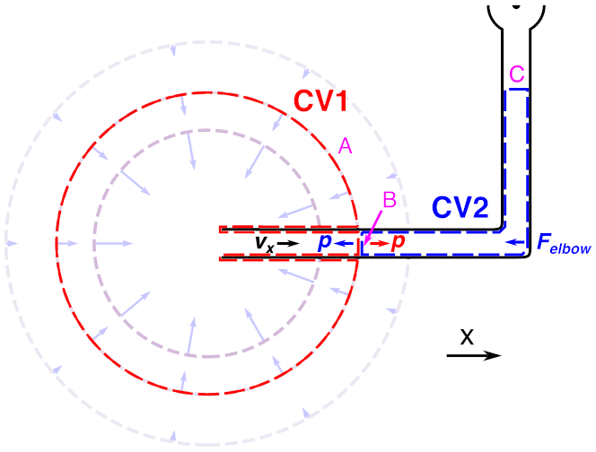
We define the pressure on the spherical shell A to be zero (assuming spherical symmetry, the pressure on surface A is constant, and then we can choose our pressure gauge such that it is zero). We also assume that the net x-momentum of entering fluid parcels is zero, since fluid comes from all directions3.
Thus, in CV1, fluid parcels enter through surface A with no net x-momentum and exit through surface B with net x-momentum. Where does this x-momentum come from? It comes from the negative pressure force on the surface B (ultimately the sprinkler suction).
First, let us neglect forces with the pipe in CV1. We write a momentum balance equation as follows. This is written in the conventional order to mirror Reynolds’ transport theorem for material elements, but it is simply a statement that any change of momentum in CV1 is due to either external forces on CV1 or fluid flow through the boundary (convective momentum flux):

(For steady state flow, we can assume that the d/dt term is zero, i.e. CV1 is not changing momentum, since a finite volume of space cannot be continuously gaining or losing momentum. Thus any momentum change from external forces [left hand side] must be carried out by the flow of the fluid [right hand side].)
Now in CV2, the fluid parcels enter through surface B with net x-momentum and exit through surface C with no net x-momentum. The fluid ‘hits’ the bend, so it might seem like there should be a force on the pipe elbow. But remember that pressure is isotropic, so the B surface of CV2 has the same pressure forces as CV1 but in the opposite direction, which cancels the x-momentum flux into CV2. The momentum balance holds with exactly zero net force on CV2 from the elbow, hence zero net force on the elbow from CV2.

Consider now if the pipe exerts forces on the fluid in CV1, such as frictional forces, which we combine as a force Fpipe:
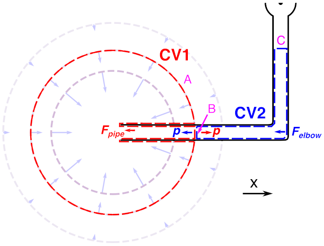
In CV1, the momentum balance is now like this:

Again I have written this in the usual order, but if you look at this right-to-left, you can think intuitively about retarding forces from the pipe (such as friction) taking away from the velocity that would be achieved for a given pressure.
Adding equation (2) and (3):

That is, the horizontal forces on the fluid from the pipe add to zero, and so the horizontal forces on the pipe from the fluid must also add to zero. If there is a force on the fluid in CV1 (due to frictional forces and/or pressure forces at the inlet), the forces at the pipe elbow change correspondingly. If there is a force on the pipe in CV1 (due to frictional forces and/or pressure forces at the inlet), the forces on the pipe elbow change correspondingly.
This may seem like algebraic tomfoolery, but it reflects the local mechanisms behind the global momentum conservation argument made earlier: forces and velocity are coupled so that momentum is conserved. In this case, if the initial and final mean x-velocities are zero, then the horizontal forces must also add to zero.
In this idealized treatment we did, however, make several assumptions. Most significantly we assumed that the pipe inflow was spherically symmetric, which is not actually a good approximation close to the sprinkler. We will make this all a little more rigorous and general in part 2.
- The construction in Jenkins’ original paper relies on the fluid gaining velocity within a pipe of constant cross-section, which cannot satisfy mass continuity. ↩︎
- By net momentum flux I mean the net inwards momentum flow considering both pressure forces and velocity of fluid parcels (convective momentum flux). Indeed if the flow is spherically symmetric then both of these quantities separately add up to zero. ↩︎
- It might seem that we need to consider the hole in the shell where the pipe pierces it. We will show in part 2 that the net momentum flux sums to zero nonetheless, assuming that the pipe is not infinitely long. In the meantime you could consider making the pipe diameter arbitrarily small, or consider that the velocity outside the pipe (which falls off as r2) is negligible compared to the velocity inside the pipe. ↩︎
