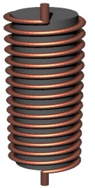
Consider a solenoid made of wire wrapped around a rod made of iron, ferrite, or other ferromagnetic material:

It is well known that the magnetic field will be significantly stronger inside such a solenoid, compared to an air core solenoid. The ferromagnetic core becomes temporarily magnetized and reinforces the magnetic field. But what I’m more interested in is: what is the effect of the ferromagnetic core on the field outside the solenoid, some arbitrary distance away? This question is interesting when using such a coil as part of a magnetically-coupled data or power transfer system, or when considering the electromagnetic interference produced by such a solenoid.
Some sources seem to suggest that the field will be confined more closely when a ferromagnetic core is used, as is the case for ferrite-core transformers. Other sources seem to suggest the opposite, namely that the ferromagnetic core increases the range of the field. Meanwhile a naive application of the Biot-Savart law would suggest that the field outside the solenoid does not change. Which of these is true?
Simulation
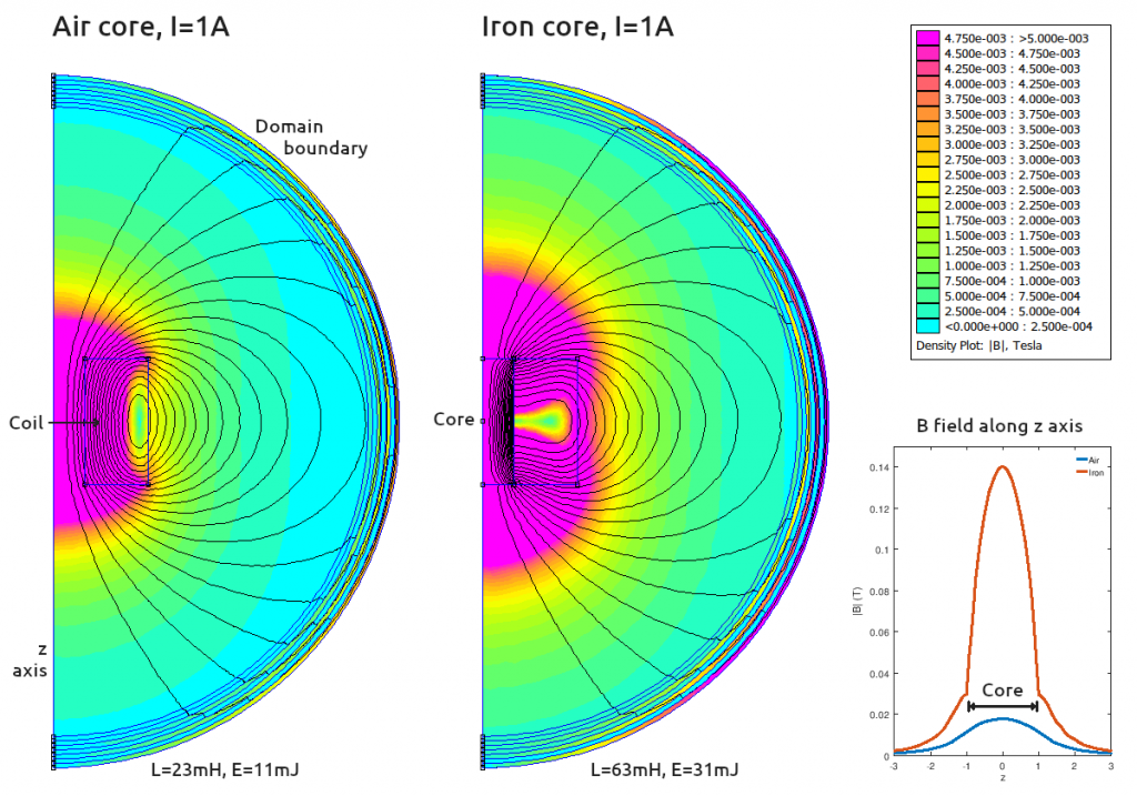
To answer this question, I ran a simple simulation with and without an iron core in the excellent FEMM field solver. Here is a picture of the results:

This is an axisymmetric simulation around the z axis. To picture the results in 3D, mentally revolve the half-circle about the z axis at the left. The outer sphere can be ignored, it is just the boundary of the simulation volume.
The conclusion from the simulation is that — at least for a fixed current — the magnetic field is higher outside the solenoid (at any given distance) when an iron core is added.
But surely as we learnt in physics classes, we should be able to calculate the external magnetic field by summing up all the current elements of the solenoid, per the Biot-Savart law? Why does adding an iron core make a difference?
I believe the explanation is that there are “bound currents” at the boundaries of the iron core which also need to be included in any such piecewise calculation of the magnetic field. This stackexchange answer has some good diagrams that help to explain how these bound currents come about.
Constant energy comparison
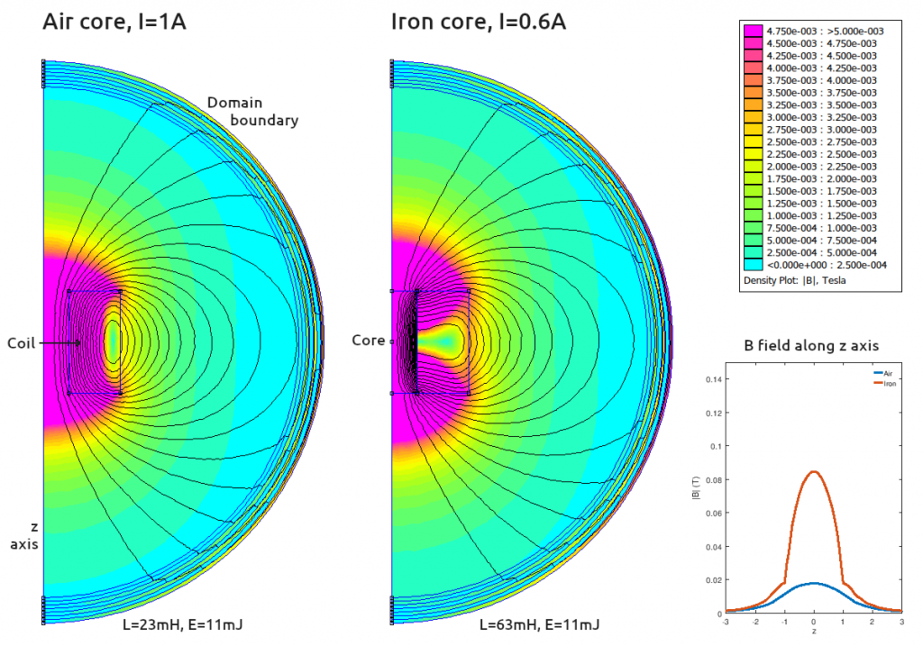
Now it should be noted that the above simulation has assumed a constant current of 1A in both cases. When the iron core is added, the inductance of the solenoid increases and we had to pump more energy into the solenoid to produce this 1A steady state — so perhaps it’s not surprising that the field is stronger outside the solenoid. To make a more “fair” comparison, I reduced the current through the iron core solenoid to produce the same total energy storage:

Notice that, at least for this geometry, the external magnetic field is still higher at any given distance.
“Return path”
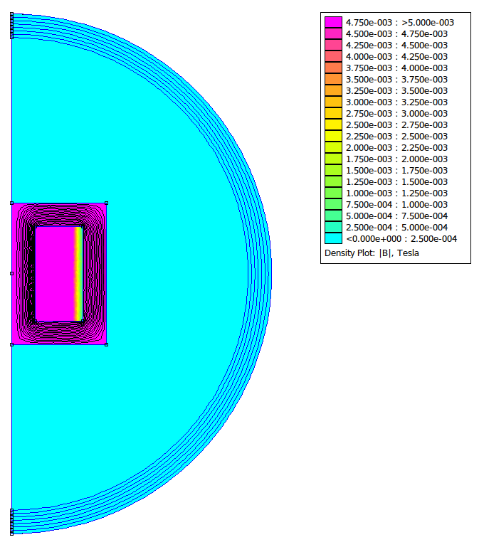
So why do people consider iron/ferrite cores to confine fields more tightly? Well, the issue with the above solenoid design (or perhaps feature if you are trying to increase range) is that the return path of the magnetic field lines is through air and not through iron. We have boosted the magnetic field within the iron, but we’ve ended up with most of the field energy in the air.
If we were to put the iron all the way around the solenoid, which is closer to the usual design of transformers, the result does indeed confine the fields tightly (N.B. I have used the same colour mapping here so that it can be directly compared):

I hope that this post helps to clear up some confusion and might be of help the next time someone is searching for information about the external magnetic fields of ferrite core solenoids (like I was earlier today)! If you think I have got anything wrong, please let me know.

 BETA
BETA
Hello, and thank you for sharing!
In your last example, is the current also 1A? I am confused because according to the last case (with the return path) the magnetic field inside the core is the same as before, without any return path (B=4.75*10^-3 tesla). I would have expected it to be way more high with the return path, because the field lines can now all travel through a very high permissible material..
Hi Sven,
Yes you are right, sorry for the confusing graph. The purple colour is anything larger than 4.75 mT. In fact, the magnetic field inside the iron core is much larger that that: 140mT in the open solenoid case (see the little graph on the right), and you are right that it is even larger with the return path. My purpose here was to show how the field outside the solenoid changes.
Best regards, Matt
Thanks for the reply!
I understand you where trying to show something differently. I am just currently working on a problem using solenoid actuators and I saw that they always seem to have a return path for the flux.
I just wasn’t sure why… I assumed it would result in a larger field inside, but actually I’m not that sure. It could also just be for protection, mounting options, EMC reasons, etc…
Do you happen to know how much more the field was with the return path? That would be valuable information for me.
Thank you
Hi Sven,
I just ran the simulation again, the magnetic field inside with the return path is 2T at 1A (>>140mT without the return path). Note though that the inductance is also much higher, so you have to put more energy in to get that field.
I think you are right that this is helpful for solenoid actuator design. The force on the armature is related to the dL/dx as the armature moves into the solenoid, and by having a closed iron-iron path you have a high inductance when the armature is completely inside, but a much lower inductance due to the air-iron path when the armature is not inside. (This difference will be more than the difference between iron-air vs air-air.) It does also help with protection, mounting, EMC, …
I also found this answer: https://physics.stackexchange.com/questions/48427/does-the-shielding-around-a-solenoid-actuator-affect-the-force-on-the-plunger
Best regards, Matt
Thank you very much!
kind regards,
Sven