
 BETA
BETAThe decryption function
If you are just joining this story you may want to start at part 1.
In part 2, we discovered that a embedded controller update is performed by uploading a small ‘flasher’ program to the EC. This flasher program is then responsible for programming a new firmware image to the EC’s internal flash memory. However, both the flasher program and part of the firmware image are encrypted: the old (currently running) EC firmware decrypts the flasher program, and the flasher program then decrypts the new firmware update. This creates a bit of a chicken-and-egg problem that prevents discovering the encryption algorithm from firmware update files alone.
We managed, however, to find a decrypted version of the EC firmware online, dumped directly from EC flash memory via JTAG. Let’s dive right in and disassemble the decryption function that can be found in that flash image. The core of it looks like this:
2854:  30 25 8d 1f 00 00 48 14      ld         r13,[r13,0x1448]
285c:  30 21 81 0f 00 00 48 10      ld         r1,[r1,0x1048]
2864:  cf 7e                        extb_s     r14,r14
2866:  02 be                        asl_s      r14,r14,2
2868:  b9 61                        add_s      r1,r1,r13
286a:  30 26 8d 1f 00 00 48 18      ld         r13,[r14,0x1848]
2872:  4f 7f                        extb_s     r15,r2
2874:  02 bf                        asl_s      r15,r15,2
2876:  a7 79                        xor_s      r1,r1,r13
2878:  30 27 8d 1f 00 00 48 1c      ld         r13,[r15,0x1c48]
2880:  b9 61                        add_s      r1,r1,r13
Here each input byte is transformed through a lookup table (in cryptography terminology, a substitution box or ‘S-box’) and the results are combined with an add/xor/add structure. This is the Blowfish cipher, as becomes evident from one glance at the diagram in the Wikipedia article on Blowfish:
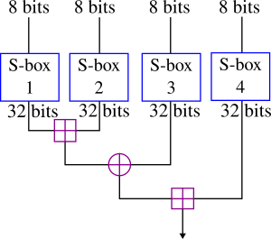
[Diagram by Decrypt3/DnetSvg via Wikimedia, CC BY-SA 3.0]
Now normally the first stage of Blowfish, like most ciphers, would be to expand a user-provided key – a password or passphrase or some other secret data – to produce a set of 18 round keys (called the ‘P array’ in Blowfish terminology) and the four 256-entry S boxes depicted above. In cryptography this expansion step is called a key schedule.
In the case of the Lenovo firmware, it turns out that the keys are stored in pre-expanded form, i.e. the values of the P array and S boxes are stored in flash memory rather than the original key string. We can extract the P array and S boxes from the dumped flash image and use them for encryption/decryption.
(I do not believe there is any easy way – where in cryptography easy means ‘significantly better than trying all possibilities’ – to recover the original key string that was used to generate the P array and S boxes. This would be an interesting challenge, but is of purely academic interest: the P array and S boxes are all that is needed for both encryption and decryption. Each round of Blowfish involves taking the data, mixing in [exclusive or] one of the round keys from P and then performing the function depicted above using the S boxes; this is repeated 16 times; apart from some minor details you now understand how Blowfish works.)
The checksum function
Having the encryption algorithm and keys, we can now decrypt the flasher program that is uploaded to the embedded controller when performing a firmware update.
Analysis of the flasher program allows us to determine the checksum algorithm used to validate the firmware image. Even without a detailed analysis of the disassembly, we can notice that it uses the following table:
uint16_t csum_table[256] = {
 0x0000, 0x1021, 0x2042, 0x3063, 0x4084, 0x50A5, 0x60C6, 0x70E7,
 0x8108, 0x9129, 0xA14A, 0xB16B, 0xC18C, 0xD1AD, 0xE1CE, 0xF1EF,
 0x1231, 0x0210, 0x3273, 0x2252, 0x52B5, 0x4294, 0x72F7, 0x62D6,
 0x9339, 0x8318, 0xB37B, 0xA35A, 0xD3BD, 0xC39C, 0xF3FF, 0xE3DE,
 ...
};
A quick Google for these numbers gives this secret away easily: this is a lookup table for a CRC-16 function with a generator polynomial of 0x1021. At this point we can be pretty sure that the algorithm is CRC-16, with only a few details to determine like initialisation value, but let me indulge myself and make a brief digression into what a CRC is and why the table looks like this. You can skip to the next section when this gets too dense for your liking.
The first thing to note is that when people refer to a CRC-16 generator polynomial of 0x1021, what they actually mean is 0x11021, i.e. binary 10001000000100001, i.e. x^16 + x^12 + x^5 + 1. (The x^n term of a CRC-n generator polynomial is always assumed to be 1, otherwise the following algorithm would not produce an n-bit CRC.)
Now the best way to imagine calculating a CRC is, for every 1 bit that is set in the input message, you XOR in the polynomial (towards the right, if working left to right). This clears that bit and flips some subsequent bits: for the above polynomial, it flips the three bits at N+4,N+11,N+16. If those bits end up as 1 (when you come to them), they will in turn propagate to other bits. Once you reach the end of the message, you’ve cleared all the bits in the message, but you have some bits hanging off the end: these are the CRC. You can intuitively see from this that the CRC has error propagating properties; an erroneous bit will likely cascade to many other bits. (Engineers might be reminded of a linear feedback shift register which has many similarities. The CRC can also be expressed mathematically as the remainder of a long division in carry-less binary arithmetic [GF(2)], the similarity to long division will become apparent in the examples below.)
As an example, if the input message to our CRC is one byte with value 5 (00000101), then the CRC calculation would proceed like this, where I have highlighted in red the leading 1 at each step:
        (5)  00000101|
              xor 100|01000000100001 (0x11021)
             -----------------------
             00000001|01000000100001
                xor 1|0001000000100001 (0x11021)
             -------------------------
             00000000|0101000010100101 (0x50a5)
Here is another example for an input byte with value 16 (00010000):
       (16)  00010000|
            xor 10001|000000100001 (0x11021)
             ---------------------
             00000001|000000100001
                xor 1|0001000000100001 (0x11021)
             -------------------------
             00000000|0001001000110001 (0x1231)
For larger messages doing this bit by bit would be slow, of course. To do it more efficiently we can pre-calculate the effect of a byte on the next sixteen bits (this will be some pattern of bit flips), for each of the 256 possible values of that byte. We then look up the first byte, XOR that in to the next sixteen bits, move to the next byte and repeat. Actually the “effect of the first byte on the next sixteen bits” is exactly equivalent to the CRC of that byte – the CRC is the pattern of bit flips that ends up past the end of a message – so the lookup table is in effect a table of CRCs of single bytes.
Looking at the above examples you can verify that the CRC of 5 is indeed the entry with index 5 in the table above, and the CRC of 16 is indeed the entry with index 16. If you stare at the first example for a moment, you might see why the first sixteen entries of the table are multiples of 0x1021: all the 1 bits in 0x11021 are far enough apart that the input bits propagate independently into the CRC. Things change at entry 16 because the next 1 in the polynomial crosses over into the message.
Now, back to your regularly scheduled programming
Returning to the firmware, we can verify that the flasher checksum is in fact CRC-16. It’s important to note that the flasher program calculates this checksum after decrypting the firmware image, so the CRC-16 must be calculated on the decrypted version of the image. (It turns out that the firmware image is encrypted using the same key as the flasher program, so at this point we already have everything we need to know.)
I mentioned in part 2 that a simple 16-bit checksum is also present at the very end of the firmware image. In fact, there is also a third type of checksum that we discover when we disassemble the EC boot code: four 32-bit checksums, each performed on a different area of the flash memory.
Summarising now, the three EC checksums that must be correct are:
- The outer checksum: BIOS checks the checksum of the (encrypted) image before uploading it to the flasher. The last two bytes of the image are calculated such that the total sum of the 16-bit words of the image is zero. If this fails, flashing doesn’t proceed, so this is the least dangerous checksum to fail.
- The flasher checksum: The flasher calculates the CRC-16 checksum of all the decrypted bytes except the last four bytes. The penultimate two bytes of the image contain this checksum. If this checksum fails, the flasher sets a flag in flash that causes the EC firmware to fail to boot.
- The boot checksums: The EC firmware, at boot, calculates 32-bit checksums of four different areas of the flash. If any of these fail the EC firmware fails to boot. These checksums must, of course, also be calculated on the decrypted image.
Building a modified firmware
We now have everything we need to know to successfully modify the embedded controller firmware. Returning to my original goal, here is the change I made to the battery authentication check (before/after, with some comments added):
  ; call validation function on battery response
  1d168:   ee 0f af f2         bl.d       0x2954 ; validate
  1d16c:   f8 16 02 11         ldw        r2,[r14,248]
- ; branch to failure path if return value not equal to 1
- 1d170:   0b 08 51 00         brne       r0,1,0x1d17a
+ ; branch replaced with no-operation instruction
+ 1d170:   4a 26 00 70         nop

  ; success path - set bit 3 in battery status
  1d174:   00 86               ld_s       r0,[r14,0]
  1d176:   83 b8               bset_s     r0,r0,3
  1d178:   24 f0               b_s        0x1d1c0

  ; failure path - try a different validation function,
  ;                else retry up to 8 times, else abort
  1d17a:   10 10 80 20         ldb        r0,[r16,16]
  ...
Previously, if the return value from the validation function was not equal to 1, the code would branch to a failure path. I replaced this conditional branch instruction with a no-operation instruction so that, regardless of the validation result, execution would fall through to the success path. (This technique of replacing jumps with nops is a common trick when you need to modify the behaviour of binary code.)
(At this point my focus was on the first authentication sequence – state 12 in the firmware state machine that I listed in part 2.)
Also, for fun and so I could track my modified firmware version, I changed the embedded firmware version from “GCHT25WW” to “GCHT25MC”. I thought putting my initials in the geographic region field would be appropriate: the original suffix, WW, presumably means worldwide, while this firmware had… somewhat more limited geographic reach.
Having made my changes, I wrote some small utilities to regenerate the three types of checksums – I have published these utilities on GitHub – and finally I re-inserted the modified embedded controller firmware into the BIOS update .FL2 file at offset 0x500000.
If you are attempting this, make sure you check and double-check that you’ve modified exactly what you intended to modify. For Linux users, process substitution can be handy here, e.g. to get a binary diff of two files you can do: diff -u <(xxd file1.bin) <(xxd file2.bin).
The moment of truth?
I ran the BIOS update program and was greeted with:
An update is not necessary at this time. The process has been canceled.
Thwarted. I was already running the latest BIOS version and the update program did not offer an option to force an update of the BIOS or EC. Downgrading and upgrading might usually be a workaround, but I wasn’t sure that this would be possible as the Lenovo release notes mention that, “if the UEFI BIOS has been updated to version 2.63 or higher, it is no longer able to roll back to the version before 2.63 for security improvement”.
Fortunately, it turns out it’s possible to run the update program manually, bypassing the limited user interface.
Manually updating the EC
A note: As I do not have Windows on this laptop, I am running the BIOS update program from a USB flash drive following some instructions I found online (in short: download the bootable CD image; run geteltorito -o bios.img gcuj23us.iso; write the bios.img file to the USB stick). I suspect the below process is even easier from Windows, where you can directly run winflash32.exe or winflash64.exe in place of dosflash.exe.
The Lenovo BIOS update CD is just a DOS boot disk at heart. If you’ve written it to rewritable media like a USB flash drive, you can edit autoexec.bat to stop it starting the user interface, in which case it will drop you to a DOS prompt.
Updating the EC firmware can be performed using dosflash.exe as follows (/sd is skip date check to allow downgrading, /ipf ec targets the EC area):
C:\FLASH> dosflash /sd /ipf ec /file GCETA3WW\$01DA000.FL2
SCT Flash Utility for Lenovo
for Shell V1.0.1.3
Copyright (c) 2011-2012 Phoenix Technologies Ltd.
Copyright (C) 2011-2012 Lenovo Group Limited.Read BIOS image from file.
Initialize Flash module.
Read current BIOS.
Oem checkPrepare to flash “ec”
Do not turn off computer during the update!!!
Begin Flashing……
Total blocks of the image = 48.
|—+—-+—-+—-+—-+—-+—-+—-+—-+—-|
…………………………………………..
Image flashing done.Flashing finished.
BIOS is updated successfully.
WARNING: System will shutdown or reboot in 5 seconds!
A note here on the FL1 and FL2 files since I couldn’t find any explanation about this on the Internet: the FL1 file is a UEFI capsule file that contains the BIOS. The FL2 file contains embedded controller firmware at offset 0x500000-0x530000, the rest of it can be ignored. Why then is the FL2 file so large and why does it contain bits of an old BIOS version pasted after the EC firmware? I think partly it may be to appease the non-Lenovo-specific parts of dosflash.exe. I noticed that even though ultimately it only uses the 48 4KB blocks from 0x500000-0x530000, if I pass a file that ends there, dosflash.exe does not recognise it as a valid BIOS update file.
(While the command shown above updates the EC, I will note here that it is also possible to update the BIOS in a similar way, by omitting /ipf ec and by specifying the FL1 file instead of the FL2 file: dosflash /sd /file GCETA3WW\$01DA000.FL1
Of course I recommend using the the normal manufacturer-recommanded BIOS upgrade/downgrade process when possible, but this may be useful if you are in a bind.)
Note that, despite what the output of dosflash.exe says, the actual EC firmware is not updated yet: at this point it has just written the update to an area where it can be picked up by BIOS at boot. Now after reboot the screen displays:
Flashing Embedded Controller…
Please do not power off!
(I appreciate the ‘please’, but really that should read “DO NOT UNDER ANY CIRCUMSTANCES POWER OFF, EVEN IF YOUR HOUSE IS ON FIRE AND SOMEONE HAS STOLEN YOUR PANTS”.)
A few skipped heartbeats later, the firmware update completes.
The moment of truth?
Sure enough, the system is now running my modified embedded controller firmware.
But my battery still isn’t charging. I hook up the SMBus signals to my logic analyser again and the communication looks like this:
...
START 16 (Control Byte: Slave Address B Write) 3C 04 NACK STOP
START 16 (Control Byte: Slave Address B Write) 3C 04 NACK STOP
START 16 (Control Byte: Slave Address B Write) 3C 04 NACK STOP
START 16 (Control Byte: Slave Address B Write) 3C 04 NACK STOP
It turns out that it isn’t even getting to the authentication check that I had modified, because the earlier command that sends the challenge to the battery is failing: as soon as the laptop sends command 3C and the data length indication 04, the battery is signalling NACK – not acknowledged – go away. So now I modify the state machine so that it proceeds whether or not that write command succeeds (again I do this by replacing a jump by a nop, this time in state 8).
Revision two deployed. Now the system boots with:
The battery installed is not supported by this system and will not charge. Please replace the battery with the correct Lenovo battery for this system. Press the ESC key to continue.
Well, that’s some sort of progress: at least it is no longer displaying the original unauthorised battery message.
I look in BIOS to see where these messages are coming from. Both this message and the original unauthorised battery message are displayed by LenovoVideoInitDxe.efi: don’t ask me why this code is in this module rather than somewhere more relevant (may I suggest LenovoAnnoyingBatteryMessageDxe.efi?), but it might have been convenient to put it in the video initialisation module as the message is displayed when the screen is cleared post-POST.
Anyway, in LenovoVideoInitDxe.efi it reads the battery status from the EC (register 0x38, which we came across in part 2 when decoding the ACPI tables, as well as register 0xd1 which has some additional battery status flags). Depending on certain bits in those registers, it may print one or other message.
Tracing through the EC code to find where those bits are set proves difficult, so I again hook the battery up to my logic analyser. It becomes evident that the sticking point is now the second authentication sequence.
I now make the same changes to the second authentication sequence as I did for the first: I prevent the write command from failing even if the battery NACKs it (state 15), and force the check of the response to succeed (state 19). This is now four changes in total, for each of which I’ve replaced a jump with a nop.
After booting to this final EC firmware revision, my saga comes to an end, almost anticlimactically. My replacement battery works, and I’m getting a good few hours out of it (and no, it hasn’t burst into flames).
Postscript
There is still one very curious open question that I haven’t managed to figure out. There are 10 random-looking bytes at offset 0x200 of the firmware image – the start of what looks like a firmware information block – which are different in every EC revision. So far I haven’t found anything that accesses those bytes, and indeed my EC update works fine even when I leave them unchanged. Probably this is a red herring, but what these bytes are for is still a mystery.
I have uploaded my utilities to GitHub so that it is possible to replicate my work and possibly make other changes to EC firmware. (Edit, Jan 2017: Hamish Coleman has built some additional utilities around my code that may also be useful, see hamishcoleman/thinkpad-ec. If you are only interested in the battery patch you will need to disable his keyboard patches.) The exact changes I made to my X230T firmware are also available as a bspatch file here. However a large disclaimer applies to all of this: do not attempt EC firmware modification at home unless you understand what you are doing. If something goes wrong with an EC update, there is a high likelihood of bricking your laptop, the only recourse being connecting to the EC via JTAG. I will not be held responsible for this. You should also understand that poor quality lithium ion cells can cause fires, as has been seen in the recent spate of hoverboard fires. I will also not be held responsible for this.
I have since also torn down my old Lenovo battery, and I plan to write another post soon with some information and photos. The option of replacing the cells in a genuine battery may be worth considering as an alternative to modifying the EC firmware, the advantage being is that you can choose your own high quality Li-Ion cells versus whatever you might happen to get in a replacement battery. The disadvantage is that it inevitably results in some damage to the battery casing, and as I mentioned before the controller will remember data about the old cells which might affect function of the new cells (I will see what I can figure out on that front).
To be fair, buying a genuine Lenovo battery is probably the best option for most people, at least while Lenovo is still making replacement batteries for this model. Primarily this was an exercise in ‘because I can’: I and a great many readers have enjoyed this process of diving deep into the system architecture of a modern laptop, at a level that few people are normally exposed to, and removing an annoying limitation that I feel I should be entitled to remove from my laptop. I do not have anything against Lenovo specifically – they are certainly not the only vendor who implements vendor restrictions – so please be nice in your comments.

A special shout out to reddit user kernel_task who ‘worked ahead’ and worked out the encryption algorithm ahead of me posting part 3!
Hey, kernel_task here. Thanks for the shout-out!
I actually got interested in the question of whether or not it would be possible to derive the original Blowfish key from which the P array and the S boxes were generated. I did some boolean algebra and it turns out there is.
In fact, the P array alone is sufficient to derive the key. I wrote some code here: http://pastebin.com/L67T4aXR
All you would need to do is solve for the values of the P-array before blowfish is done over and over again to initialize the P-array with their eventual values, and then XOR them with the initial P-array values for the algorithm (the ones derived from digits of pi). You would then recover the key bits and by looking for repetition you can guess how many bits the key was.
Solving for the values of the P-array before blowfish is performed can be done backwards, starting by figuring out the initial values of P[16] and P[17]. Those rely on the fact that the encryption to generate them uses the initial S-boxes and uses the final values of P[0-15], which are known. The only steps involving the initial values of P[16] and P[17] themselves is just a XOR and a swap, which could easily be reversed.
Then I solve for P[14] and P[15] by running the encryption forward until the round requiring the initial values of P[14] and P[15]. Then I run the encryption backwards from the final values of P[14] and P[15] (which are known) until that same round. Knowing both the state before the round requiring P[14] and P[15] and after it means that I can figure out the initial values of P[14] and P[15]. This is done until I solve P[0] and P[1].
For the P-array in the “Lenovo THINKPAD X230 mec1619” dump in that thread, the key happens to be this: 964c64a9fe22db7a4afe9fd50a84fb0a6126e3d7a21986d8b8fb49913a9691bb
Awesome job on the rest of the project!
Wow, fantastic work! I thought it wouldn’t be possible to do without brute force but it turns out that I was wrong, the Blowfish key schedule can indeed be reversed using your method. I’ve verified that key indeed works.
my laptop is E130, help me to pach EC dump https://www.dropbox.com/s/tylcqq4409jovb9/E130.rar?dl=0
booting message
The battery installed is not supported by this system and will not charge.
Please replace the battery with the correct Lenovo battery for this system.
Press the ESC key to continue.
Wow.
Just…. wow.
Thank you, Matthew. Now I want to buy a new Lenovo device and a different battery just to try it myself.
Thanks mate, good work.
Just wanted to point your attention to a posting in the comments of Part 2 which covers replacing the LiIon-cells:
http://www.zmatt.net/unlocking-my-lenovo-laptop-part-2/#comment-47935
Lenovo really does not want the users to mess with the hardware. 😉
That has nothing to do with Lenovo – that is a standard lithium battery undervoltage protection circuit kicking in. It is supposed to lock out a battery that got discharged below a safe limit, e.g. because of old age. Attempting to charge such battery could cause a battery failure – explosion, fire, etc. – so that is why this circuit disables it.
When you are replacing the cells you must be aware of this circuit and keep it energized or replace it. Some can be reset as well.
This function is sometimes used to hard-kill old batteries. I have a Dyson DC31 pack that, as it’s last act, discharged all the cells to around 0.5v each. Good for disposal, a right pain if trying to repack it. It’s an authenticated pack too.
Excellent job and a lot of different skills successfully used; I’m envious 🙂
Thanks for sharing.
UEFITool author here. Very nice work, thanks for cracking that encryption.
Oh hi, thank you for UEFITool. Over the years I’ve used a couple of different scripts for pulling apart EFI capsules and they’ve all had different issues/limitations, UEFITool worked for me out of the box, so thank you.
My pleasure, I like when someone finds it useful.
This vaguely reminds me of the time I wanted to simply watch a DVD but instead spent the next few hours hacking the Windows display driver because it disabled screen output on my (pre-HDMI) TV when DVD playback was requested. So I perfectly understand where you’re coming from, but still, this amount of effort is pretty insane 🙂 And I had an incredibly good time reading it, so thanks a lot for your detailed description!
I subscribed to the RSS feed so I don’t miss part 3 and I will keep it in case something else bugs you in the future 🙂
Lenovo may not be the only vendor implementing spare part restrictions, but they (presumably) are the last one to join the party, and thus currently get to bear the blame.
I assume, one reason for this change is that improvements in hardware performance are slowly declining in recent years. Where you had to buy a new PC every few years to keep up with the growing demand of contemporary software, this is no longer the case now. Most business software is still happy with a core2duo system, there is no need to get the new i5 model. The only part of a laptop that is still predictably deteriorating is the battery. If it wasn’t for these pesky aftermarket battery vendors, you would be “enticed” to buy a new laptop even if you didn’t need to upgrade, simply because Lenovo stopped selling spare batteries.
Seems like they have gone the most evil route to remove their market offenders from the game of milking customers.
And there I am, until recently considering to switch from an HP Elitebook to Lenovo, since HP BIOS does vendor ID checks on wifi and 3G cards.. thanks to you I don’t have to anymore. Pest or cholera?
Lenovo also implements a whitelist for wifi/wwan. you should consider dell latitude
Depends on the Latitude model. I have a Dell Latitude E6220 and there is a whitelist for WWAN cards. WLAN cards are unencumbered though (as of BIOS A12). I think this may be due to regulatory limitations on 3/4G hardware rather than specific malice on the part of Dell.
to my understanding,thinkpad >= x250/t450 are having no whitelist anymore.
i tried myself on my x250. changing the intel wifi card to broadcomm wifi card. no error on whitelist. cmiiw.
Hi, you bring an exciting note to this discussion.
What WLAN card did you use in your replacement?
Thank you for sharing your work with us! It was a pleasure to read!
Mastermind. Weltklasse umgesetzt, Respekt.
Someone linked to this article on an irc channel where I hang out. Although it was quickly pointed out that you are in fact not me, this epic quest shows you are indeed very worthy of also using the name. Carry on 😉
BTW it’s perhaps worth mentioning that particular CRC is commonly known as CRC-CCITT (assuming it’s also initialized the same). Also, checking an appended CRC can normally done by calculating the CRC over the area including the CRC and checking the result to be zero (assuming no post-inversion). Another useful property for patching is that crc(a ^ b) = crc(a) ^ crc(b) ^ crc(0) where all inputs are taken to be the same length (xoring crc(0) is only needed if non-zero initialization or post-inversion is used). This allows updating the CRC for modifications even if part of the input is unknown.
Matt, standing ovations !
But … does the Coreboot und Libreboot folks know about your story and methods ? As far as I know they only succeeded in building new firmwares for the Thinkpads X200 and T400 so far. There are lots of people hungry to replace the Intel Management Engine and other questionable stuff from their Thinkpads (who likes “remote administration” tools which some people call backdoors ?).
Tom
Lenovo a good manufacturer. But its battery on my B 560 worked just six months .. Thank you for persistence ..
I am wondering if it might be a good idea to replace the checksum-checking code sections as well.
When I understood correctly, the flasher program is included in the “firmware file”. So when you modify it so that it does not check the checksum of the encrypted section, you could get rid of some other steps!?
I’m wondering if a similar method could be employed to flash a modified UEFI Bios instead of EC firmware. That would free us from the wlan whitelist curse and you would get the eternal gratitude of millions of people 🙂
The folks over at bios-mods.com produced whitelist-free bioses for the X230, but they have to be hardware-flashed because of the checksum issue, I believe.
Thats exactly my thoughts.. I do have a hardware flasher but my E530 board grounds the pins in such a way I need to desolder the flashchips.
Anyway, people want to remove whitelists, remove Intel ME and install core/libre-boot. I think based on bios-mods.com that the bios flash updater used crc and encryption on parts of the normal bios (UEFI) aswell. and only somewhat after 2.5 (lenovo) changed to only update .efi files that needs updateing. but I might be mistaken.
What this does make it intrestingly is would this allow me to fix a crc bug I have in my bios and change a .efi file with a older version? (say, replace the whitelist efi file or the battery check file LenovoVideoInitDxe.efi?
Not sure about intel ME, but would the chipset lock if we corrupt/remove the firmware? hold the cpu on reset? if not, remove ME from image. Its fun anyway, Ill keep following this and try some things myself (Me want cheap 5Ghz wlan card and no more ME).. maybe coreboot
My modifications have been entirely on the embedded controller side (the FL2 file), I haven’t needed to modify the BIOS (the FL1 file, the part that runs on the main processor). I suspect that programming an unauthorised BIOS could be more difficult.
I think there already is a possibilty to flash a modified bios but I’m not sure if it works with every Lenovo notebook. You can take a look here: https://forums.lenovo.com/t5/Lenovo-P-Y-and-Z-series/Guide-BIOS-Downgrade-from-5FCN95WW-to-5FCN35WW/td-p/1781189/page/2
Quote: “It will allow you to flash your modified WPH file with wrong checksum.”
Maaan, you are cool!:)
And the _really_ sad part. Lenovo, had they wanted to be customer friendly instead of hostile, could have simply dropped the charge rate down from “super fast charge” to the regular slow “trickle” charge that every other laptop performed up until the “invention” of the super fast charging.
You put in a battery that ‘authenticates’ – you get the high speed charging.
You put in a battery that does not authenticate – you get the old slow trickle charging.
But no, they took the customer hostile route instead.
Yep. I’ve seen it claimed that the reason for the authentication is because it’s too dangerous to rapid charge batteries of unknown quality/protection, so that seems to be the obvious solution…
FYI your publications will not download in Android cgrome due to html compatibility problems.
I couldn’t reproduce this on my Android phone, but I’ve fixed the website so it now passes the W3C validator, so hopefully it will now work! Let me know if you still have issues.
You did an awesome job! I hope you inspire more people!
Matthew, amazing! Thank your for this deep dive )
I have another issue. ASUS laptop always charges battery up to 100%.
How to stop charging at 90% for prolong life ?
Any thoughts ?
There is no software from ASUS to do that.
Great article! Thank you!
Hello.
Awesome work. What about your utilities?
Thank you!
Utilities are up now.
Awesome write up – looking forward to the teardown of the Lenovo battery write up.
I m not sure, but I doubt that there are laws against not charging unauthorized batteries. I am fairly sure that they could be held liable for any damages caused by fires, etc caused by trying to charge a poorly-made battery, and that you cannot release that liability with any kind of boot-up message or contract.
Great work, is it possible to replace the keyboard rom with that from previous xx20 series, so that the xx30 could get the classic thinkpad keyboard instead of the chiclet keyboard. Willing to donate if it can be done.
It’s not quite as easy as copying a keyboard ROM, as far as I know the keyboard code is part of the embedded controller code and you can’t install xx20 EC firmware on xx30, but I think it should be possible to change the keyboard maps in the xx30 EC firmware if that turns out to be all that’s required. Just so I’m clear what you want to do, are you looking to physically install an X220 keyboard into an X230 (say)?
I, too, am interested in changing the x230 EC keyboard map.
My investigations got me as far as finding the table in the FL2 file (but not in FL1) in both an x220 and a x230 firmware package – so I can say that the changes look both simple and possible (just to head of the obvious question, yes – the hardware is completely compatible)
However, following along with your artivle, I looked at a JTAG dump of the EC firmware and was not able to find the same keyboard map table – so now I am a little more confused than I started out.
I have not had a chance to simply try using your tools and process to mod a FL2 file and flash it (partly due to time, and partly due to wanting to try and get a JTAG dump of my EC before starting)
wdbryan, I have just done this and can report partial success.
Starting with $01D3000.FL2 (version G2HT35WW and md5 68ef8766aba0aa919df9da45c1f67e86)
I made these changes to the EC keyboard mapping:
-0021960: 0000 0000 0000 0000 007b 009b 0000 0059 ………{…..Y
-0021970: 0000 0000 0000 0000 507a 9a99 9897 a054 ……..Pz…..T
-0021980: 0000 0000 0000 0000 4c4b 0000 7c00 5556 ……..LK..|.UV
-0021990: 0000 0000 0000 0000 0051 0000 0053 004f ………Q…S.O
-00219a0: 0000 0000 0000 0000 0000 0000 003c 003e ………….
+0021960: 0000 0000 0000 0000 4b7b 009b 0000 0059 ……..K{…..Y
+0021970: 0000 0000 0000 0000 4c7a 9a99 9897 a054 ……..Lz…..T
+0021980: 0000 0000 0000 0000 5556 0000 9c00 898a ……..UV……
+0021990: 0000 0000 0000 0000 5051 0000 0053 7e4f ……..PQ…S~O
+00219a0: 0000 0000 0000 0000 007c 7d00 003c 003e ………|}..
and reflashed the image.
I now have PgUp and PgDn in the right spot and a couple of other improvements.
However, PrtScr, ScrLk, Pause, Insert and Home all still dont respond. There is no immediately obvious pattern here (they are not all on the same row or column), so I clearly need to do some more checking.
Most importantly of those missing, I really want the Home key…
According to T43 EC at http://ec.gnost.info/ec-18s/split/1YHT29WW.html#fnTab1-1
You probably have 3 arrays to change:
– one for F1..F12 keys + Home/End/…
– one for combination between Fn and F1..F12 keys + Home/End/…
– one for “main” keys
You probably changed only the main array.
BTW, I’m interested to do it on the T430 EC with a T420 keymap 🙂
I’ve got that EC disassembly reference open already .. unsurprisingly, when they ported the EC code from H8 to ARC, it looks like they reorganised the tables – I cannot find any data that looks similar to those fnTab[12]
I’m not too worried about the Fn+x table (though, if I can find it, I’ll update it 🙂
My next step is to do some reading on the ARC architecture and disassemble this EC code – which is waiting for me to have enough brainspace
May I ask your email? Got something related, may be useful.
… or just write me: paul-kv (at) yandex.ru
hi matt, Great works!
btw, i build your sources in ubuntu 14.x
no problem at all.
however,
1. executing dd command as per your github give me error:
‘cannot skip to specified offset’
so after googling, i add iflag=skip_bytes
then no error message.
2. 2nd step is okay, but on the 3rd step, it give me messages:
you should run this on the unencrypted image
you should run this on the unencrypted image
6a43 06b6 FIXED
reverifying
06b6 06b6 OK
you should run this on the unencrypted image
you should run this on the unencrypted image
i tried that on the *.FL2 of X250
any hint on what i should do to make it works?
The X250 .FL2 has the image at a different offset (0x20 rather than 0x500000 – they’ve done away with the large amount of padding and just have a short header on the front). However even with that fixed I don’t think my method will work for X250. It looks like the X250 EC image is encrypted with a different key, and it looks like it may be signed (there’s 256 extra bytes on the end that may be a signature). At the very least one would need to work out the encryption key from an X250 EC flash dump, and if the BIOS verifies the signature then it might be significantly more difficult to flash a new EC image.
Good day Matthew!!! Thank you so much for the hard work and publishing your results! I have the same problem with non-genuine battery Lenovo X230i and the second problem is that I don’t know the basics of programming… But I could write the dump to a programmer if You don’t mind to send the modified dump EC by e-mail, I would be very grateful!!! Best wishes Andrew! andrey_skorohod@mail.ru
First, congradulations, this is really impressive work. In fact I got o your writing in search of a way to by pass whitelisting of WIFI cads by Lenovo. My problem is when I flash my new firmware, the chnages are not being retained… I suspect this is the checksum issue and I am wondering who should I go about having the write checksum of the amous *.FL2 so that it applies the changes…
Thanks for your help
Thanks again for your work Matthew!
Once we could decrypt and reflash the firmware with your software, a couple of us were able to replace the xx30 keyboard with a classic keyboard and keep all its functionality.
The patches for seven different Thinkpads are at https://github.com/hamishcoleman/thinkpad-ec and there is a discussion thread specifically for installing classic keyboards at http://forum.thinkpads.com/viewtopic.php?f=69&t=120776
Cheers,
Hamish.
Hi, would simply installing Coreboot be a good workaround to this problem or would it not help?
This article is the only info confirming lenovo blocking batteries in thier bios i could find. I found it because I bought a genuine lenovo battery for my B5070. The original battery is tiny at 32W. The hardware manual lists 2 batteries as compatible that are larger at 41W. So I went ahead and bought one from a 3rd party seller (no batteries for the B5070 are available for sale at lenovo online). But it doesnt charge. I get no warning at boot, only in Lenovo settings does it say that 3rd party or un-authorised batteries will not charge. I called Lenovo and I was informed that unless I purchase the exact model batter that came with my laptop (regardless of what Lenovo documentation says) there will be a high chance that it will not work.
I had already got my bios modded at mydigitallife to enable using a different wifi card, does this work by Matthew mean that it should be possible to get a bios mod somewhere to allow me to use this new 41W battery as opposed throwing it out? I don’t think I could recreate his work on my own.
This is just the perfect thriller for a Sunday morning. 🙂
Thanks a lot mate!
I wait for the next article about the battery tear down.
Great work! My knock-off ultrabay battery is humming along well now, with a custom splash screen to boot 😉
Fantastic hack/writeup! I’ve been searching the web, trying to find the knowledge to patch the EC firmware on my own computer to fix a small set of issues, and there really aren’t a whole lot of other detailed, yet easy-to-understand articles like this series. So, thanks for helping fill that void.
Interested in doing the same (battery unlock) for my recently acquired T430s – found the schematic for the T430 and it shows the same EC – MEC1619. Need to confirm that the T430s has the same, but I think it’s a good chance. I’m interested in retracing your steps and don’t currently have a logic analyzer – looks like they stopped selling the USBee SX.
I’ve worked on a Coreboot port in the past and plan on evaluating the state of the T430/T430s ports as well, not interested in deblobing / removing ME though.
Thanks a lot for posting this useful information and code!
Ahhhh!!! Iloveyouiloveyouiloveyouiloveyou!!! 😀
Finally my stupid lenovo loads my battery and i don’t have to buy such expensive new replacements for this old little fellow. =)
But i noticed, that i don’t have the normal loading behaviour under Windows 10. I don’t see the icon scrolling the battery from left to right as it does with my older one. But since i just wanted to have it work, i don’t care, just as an info. 🙂
Hello Matt,
I have a Dell Latitude E6420, where an ECE5026 is responsible for controlling the eSATA port’s power rail.
There is an another embedded controller on the mainboard a MEC5055. These two chips are connected together via BC-Link bus and each seems to be accessible through LPC from the host.
I have not found any public documentation about these chips. Do not you have accidentally any information about the MEC5055 architecture?
Does this mean we can use X220 batteries in X230 with this modded EC?
afaik the only difference between those two is drm, x230 battery works fine in x220
That’s the point.
Nice hack. I went down on a different road. I hacked the battery instead and found out (in my case) it’s a modified ti chip with a modified firmware. So it’s not working at least not 100% with the official ti software and ev2300/ev2400 interface. After I found out I made a vga-i2c adapter then on linux i wrote some userspace c code to interact with the smbus and of course download and upload the flash program and eeprom memory. In the result I brought back my original totally dead battery(cleared flags/reseted cycle count/remaining capacity) and I can still use around ~60% of the original capacity or i can say the designed capacity!
Amazing work. I was about to return a battery I just bought. Thank you.
Nice hack, thanks for sharing 🙂 My battery has decided that it’s no good when the cells are in perfect condition (BQ8055) and won’t even let my BIOS hold settings. I have pulled some smbus data and might be going for a microcontroller in the middle/battery fix for this one… (info on this chip is lacking)
Hi,
Really nice work here. Thank you for the information.
I’ve been trying to mod my X230 BIOs. Thus far I have removed the WIFI whitelist and unlocked advanced BIOS options. I’m trying to remove the battery check and I will be trying your code to see if I can manage it.
Would you be willing to share your modified BIOS so that I can “reverse engineer” it and see where you made your changes?
Thanks!
Check out the link to Hamish Coleman’s github near the end of the post, there are patches for X230 in there. Note that I only modified the embedded controller firmware and not the BIOS as such.
So you’ve successfully managed to remove the WIFI whitelist? Very cool! Would you be willing to share how you’ve done it? This bugs me to no end on my X230i.
Hi,
big thanks from germany. just updates my t430 to the current version – t430 BIOS 2.72 (G1ETB2WW) EC 1.13 (G1HT35WW) – works absolutely fine. Now my 3. party 90++ battery is working as expected.
Best Regards
Thomas
I bought a battery at Aliexpress for my Lenovo Thinkpad Edge E530c. Got the message on booting: “The battery installed is not supported by this system and will not charge. Please replace the battery with the correct Lenovo battery for this system. Press the ESC key to continue.”
I do not have the knowledge to modify the embedded controller such as done in this article. Cannot send back battery because of the costs for shipment back to China. Anybody interested in ?only for costs shipment. Living in the Netherlands
Thank you for this impressive write up and analysis of reverse engineering and patching of the firmware. You skills are highly impressive.
I thoroughly enjoyed reading through your articles.
I ran this patch on a T430, using hamishcoleman/thinkpad-ec script and it worked perfectly. (Not that I had any doubt after reading the imense amount of work went into succefully solving the issue, but I wont say I wasn’t nervous the moment of running the update).
Hi,
is anyone aware of any open source tools to read and write the internal flash of the MEC1619? Up to now, I’ve found references to SVOD programmer and JTAG Tiny Tools only. I’ve got a RaspberryPi and a Bus Pirate already on my desk, both are supported by e.g. OpenOCD. I assume I’ve fried the MEC firmware of my W530 (independently from the above changes).
Cheers,
Joerg
Oddly, if I mount the 6.6MB iso, I find the files below (totalling 5.0MB), but if I run `geteltorito -o 7luj27uc.img 7luj27uc.iso`, the .img file is only 1.5MB and contains a shorter list of completely different files (totallying 174KB).
7luj27uc.iso (for a T61):
$01AF000.FL1
$01AF000.FL2
06f1.hsh
06F1.PAT
06f4.hsh
06F4.PAT
06f5.hsh
06F5.PAT
06f9.hsh
06F9.PAT
06fa.hsh
06FA.PAT
06fb.hsh
06FB.PAT
06fd.hsh
06FD.PAT
10661.hsh
10661.PAT
10671.hsh
10671.PAT
10674.hsh
10674.PAT
10676.hsh
10676.PAT
CHKBMP.EXE
COMMAND.COM
FLASH2.EXE
lcreflsh.bat
LOGO.BAT
LOGO.SCR
PHLASH16.EXE
PREPARE.EXE
README.TXT
TPCHKS.EXE
UPDTFLSH.EXE
UPDTMN.EXE
USERINT.EXE
UTILINFO.EXE
7luj27uc.img:
AUTOEXEC.BAT
CD-DRV.BAT
COMMAND.COM
CONFIG.SYS
HIMEM.SYS
IBMBIO.COM
IBMDOS.COM
IBMTPCD.SYS
MSCDEX.EXE
QCD-DRV.COM
Continuing the previous post … When I run:
geteltorito -o 7luj27uc.img ./7luj27uc.iso
I get:
Booting catalog starts at sector: 20
Manufacturer of CD:
Image architecture: x86
Boot media type is: 1.44meg floppy
El Torito image starts at sector 28 and has 2880 sector(s) of 512 Bytes
Image has been written to file “7luj27uc.img”.
If the .iso is somehow representing itself to geteltorito as a floppy, I could see the resulting 1.44MB image; but why then is the mounted .iso not revealing the AUTOEXEC.BAT, or any of the other files, save COMMAND.COM?
Hi Matthew – wondered if you can give me some advice. I’ve got T430 and have a 27++ battery slice for it which doesn’t have the auth chip T430 looks for. Have flashed EC with Hamish’s utility and had battery validation active but it hasn’t worked, I suspect because this battery uses the dock port .
There are exposed battery pins next to the dock plug on the battery so it would be easy to connect onto the SCL and SDA pins and I could get a USB logic analyser … then I’d get into stuff way way over my head.
I’m guessing it’s not worth me trying and bricking my T430, or my head…
Do you know anyone who has worked on such a thing who might be able to help? Maybe they have a working image I could use.
Hello,
Is there a receipt how to manage this problem with Thinkpad E531?